


DCC – A Modeller’s Guide Part 2
Article from Gazette volume 20 number 6 - Feb 2018
Chris Walsh describes and illustrates how he sets up DCC decoders.
Part 2: Setting up the decoder
Many users of Digital Command Control, DCC, often do little more than reset the addresses of decoders, perhaps not realising that the decoder’s capabilities go so much further. Chris explains here how you can go further without getting too involved in the technicalities of DCC. In part 1, in the November 2017 Gazette, we looked at the physical installation of loco decoders. Now comes the exciting bit – making the loco perform the way you want it to.
When I first met John Bryce, his DCC locos were ‘doing their own thing.’ They wouldn’t set off when he turned the controller and, worse still, they wouldn’t stop when he wanted them to. 12 inches to the foot locomotives don’t accelerate up to 50 mph within seconds of setting off - and they certainly cannot stop within a few prototypical feet. But this is what we often expect on a model railway.
John’s loco decoders were supplied with momentum set up to give a prototypical response. So the first thing we did was change the CVs to reduce the momentum to zero. Problem solved…but not quite so prototypical.
Many users of Digital Command Control, DCC, often do little more than reset the addresses of decoders, perhaps not realising that the decoder’s capabilities go so much further. Chris explains here how you can go further without getting too involved in the technicalities of DCC. In part 1, in the November 2017 Gazette, we looked at the physical installation of loco decoders. Now comes the exciting bit – making the loco perform the way you want it to.
DCC – how it works
DCC is flexible enough to be able to make each
loco respond to the controller, or Cab, in a
different way. To understand how it does this –
and how to make adjustments – we need to
delve a little into the workings.
The DCC command station takes your
controller’s settings and sends them along the
track in the form of a digital signal. How it does
this is of no concern to us but the main
information it sends is:
1) which loco you want to affect (the loco’s
individual address) and
2) what you want it to do (its instruction).
To identify one loco from another, each
decoder has its own address number. All new
decoders come with address 3 as standard and,
if you have only one loco, that’s fine. No change
is necessary.
However, each of your locos will need an individual address, so the first thing you will have to set up is the new decoder addresses of all other locos. The number you choose is up to you. For convenience, I use the last digits of the loco’s running number.
In the decoder, the loco’s address is held as one of many CVs (Configuration Variables). These CVs are digital reference numbers that control what the locomotive does.
Things like: Maximum speed, Acceleration rate, Deceleration rate, Brightness and operation of lights, Volume of sound on sound decoders – even the number of chuffs for each revolution of the driving wheels.
There are a few CVs you cannot change such as the manufacturer’s code number. All the CVs are held in a memory within the decoder. We can look upon this as a block of pigeon holes. Take a look at Figure 7.
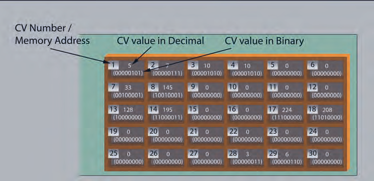 Fig 7. Part of CV memory - BR Standard Class 2
This shows some of the memory cells with information in each cell. Cell number 1 has the loco’s DCC address in it. In this case, it is number 5. Written as a binary number this is 00000101 as shown in brackets in the cell.
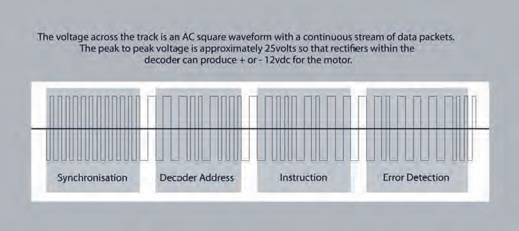 Fig 8. A typical DCC control ‘packet’
Figure 8 shows the sequence of data coming along the track. This is called a ‘packet’ and a fresh packet is sent from the command station each time you change something on your controller. It repeats the packets regularly just in case there is a problem with pick-up. As far as we are concerned, the first useful piece of data in the packet is the decoder’s address.
Let’s assume our loco’s decoder has been set up with address 5 in cell 1. The loco sits on the track reading the packets and waiting for a loco address that’s the same as in CV 1. When it sees address 5 on the track, it wakes up and thinks “Eh up, that’s me!”
Let’s also assume that you have set the controller to move the loco as slowly as possible – at speed step 1. So, the next data in the packet is an instruction to move at speed step 1. In the decoder, the start voltage for the motor is stored in CV2 (it’s actually stored as a percentage of the maximum voltage). So the decoder reads CV2 and sends that voltage to the motor.
This is very useful as it means that, by adjusting the data in CV2 in each loco decoder, you can make each of your locos move at their slowest rate at speed step 1 - no matter how much voltage the motors need to get them started.
If your next instruction is to increase the loco’s speed, a new packet is sent down the track with the same loco address but, this time, with an ‘increase speed’ instruction. CV 3 contains the acceleration rate of the loco. So the decoder looks at CV 3 and accelerates the motor at the specified rate up to the speed step you set on the controller.
Clever stuff!
Types of CV
The CVs we have looked at so far contain values. There is another type of CV that contains up to eight straight forward on/off instructions. CV 29 is one of these and to see what it does, we need to look at its binary number.
In our example, CV29 contains the binary
number 00000110. The individual digits are
known as ‘bits’ and the bit to the far right is
referred to as bit zero.
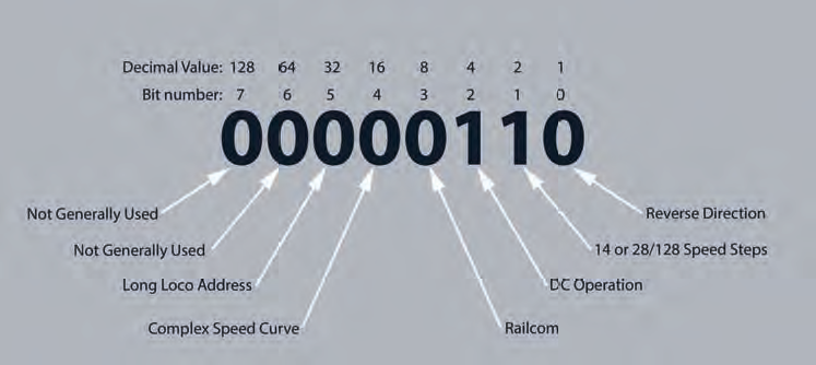 Fig 9. CV 29 Individual bit functions
Take a look at Figure 9. It shows CV29’s
individual bits and the instructions it carries.
Bit 0: Direction.
When set to 1 (on) the motor polarity is
changed.
Changing this saves you stripping down the
loco to swap over its motor connections if it
goes in the wrong direction.
Bit 1: 14 Speed Steps.
14 speed steps (set to 0) or 28/128 speed
steps (set to 1).
This is generally set at 1 to show 28/128
speed steps as the 14 speed step setting is
almost obsolete.
Bit 2: DC Operation.
When set to ‘On’, this allows the decoder to
operate on DC as well as DCC.
Sound decoders often give you the option of including some sounds on DC.
I often – although not in this case – leave
this set to 0 to avoid the chance of spurious
operations.
Bit 3: Railcom.
Unless you know you use Railcom with this
loco, leave this bit switched off.
Bit 4: Complex Speed Curve.
You can either use a simple ‘min, mid, max’
speed curve (set to 0) or a complex speed
curve (set to 1)
Bit 5: Long Loco Address.
Short (sometimes called ‘two digit’)
addressing with CV1 (set to 0) or
Long (four digit) addressing with CV17 &
CV18 (set to 1)
Bit 6 and Bit 7: These are generally not used.
Your decoder’s manual will give you details
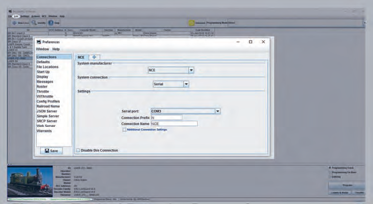 Fig 10. Decoder preferences
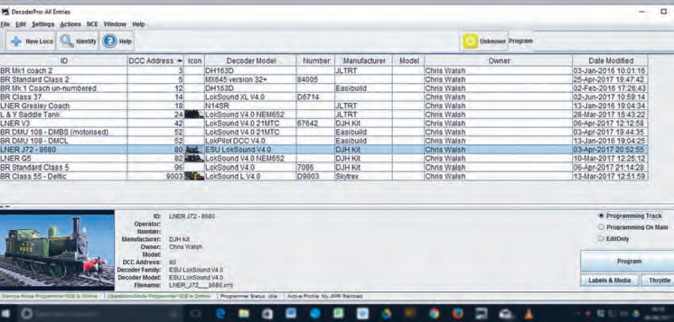 Fig 11. Loco roster
Making changes to CV 29
Changing the value of CV29 is usually done by changing its decimal value. The decimal value of each individual bit is shown in Figure 12. Adding them up gives the decimal value of CV29 which is 6.
As an example, if you wanted to switch off DC operation, you would have to change bit 2 to zero. The binary number would then be 00000010 and the decimal value is 2. So, by changing CV29 from decimal 6 to decimal 2, you have switched off DC operation.
In the same way, if you wanted to change the motor polarity, you would change bit zero to 1. This would add 1 to CV29’s decimal value – in this case, making it decimal 7.
‘Programming Track’ or ‘On the Main’
Setting the CVs can be done either on a Programming Track or on the Main Line.
1) Programming Track.
The designated ‘programming track’ is electrically isolated from the main track. The programming track output of the command station has a limited current capability so you don’t destroy the decoder if there is an electrical problem. Also, you can read the values of the CVs to see how they are set – something you cannot do when programming on the main.
2) Programming on the Main.
Programming on the main (POM) enables you to make changes to the CVs on the main track, even when the loco is moving. However, the CVs you can change are limited, you cannot change the loco’s address, for example, and you don’t have the protection of reduced current or the ability to read the CV values.
It is very useful for adjusting dynamic settings as you get an immediate effect as the loco is moving.
On my layout, the programming track is a part of the layout that passes over my workbench. It is isolated from the rest of the layout and fed from a switch so it can be connected to either the programming track output or the main line. This way, I can drive a loco onto the track, switch the section to Programming Track, make the change, switch back to Main and drive the loco off again. Changing CVs is possible using your controller but it’s an awful lot easier if you have a computer and some free software.
Setting CVs with your computer
Setting CVs can get more complicated as you get into them as we’ve seen with CV29 above. Luckily, there is no need to worry about all that if you can connect your DCC system to a computer. The NCE system at Thurlby, like many others, has a connector which enables us to make a USB connection to a PC.
If you download an app called DecoderPro®
onto your computer, you can adjust CVs easily.
You can also do other things like make a roster of
your locos and control them from the computer
if you really want to. You can even use your home
Wi-Fi to control trains with your mobile phone or
tablet - so you have a wireless control system at
no extra cost. Brilliant!
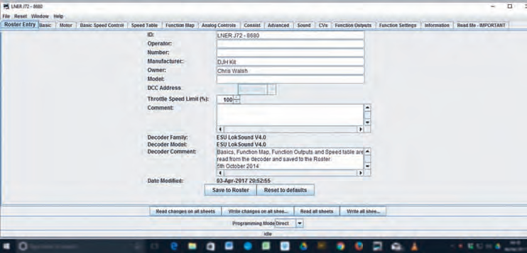 Fig 12. Roster Entry
To download DecoderPro, search for JMRI.org and follow the links. Select the latest production release for download.
DecoderPro and the other apps under JMRI are free to download. If you do use the software, they would very much appreciate a small donation - around £10 to 15 - to support the development of new versions.
But let’s get back to setting CVs through the computer…
Getting your computer to talk to the Command Station
Once you have downloaded DecoderPro and connected the command station to the PC, you will have to set your preferences. These depend on your own type of system and you’ll have to play around with the settings to get your command station and computer to talk to each other.
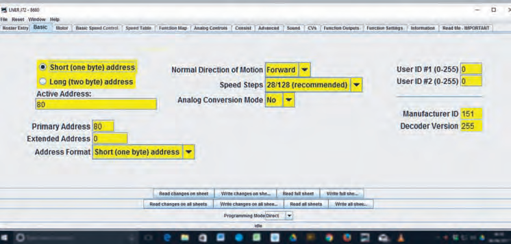 Fig 13. Basic Settings
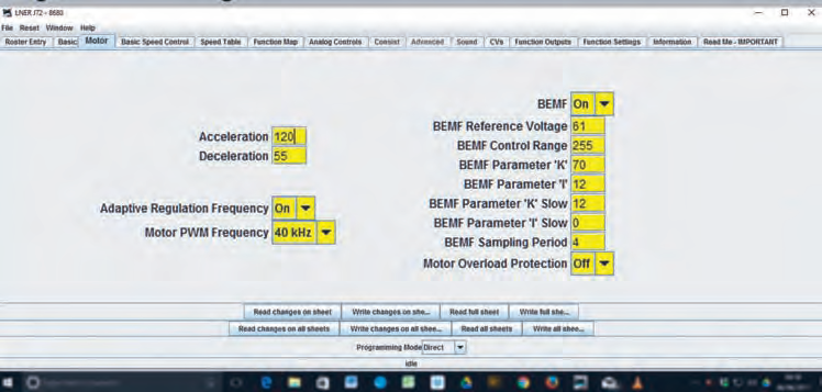 Fig 14. MotorSettings
Figure 10 shows the preference for my 5 amp Power pro system.
Start by going to Edit, at the top left of the screen, and select Preferences.
In the Preferences panel, the system manufacturer in my case is NCE and I am using a serial USB connection. So these two settings are pretty straight forward. Deciding which serial port to use depends on the settings within the computer. So I selected each of the options in turn and restarted Decoder Pro until I saw the green ‘Online’ statement at the bottom of the screen.
Having made contact between the computer and the DCC system, you can start to build up a roster of your locomotives. Place a loco on the programming track and select ‘New Loco’ from the top left of the screen (See Figure 11). The software will then interrogate the decoder. It will then present you with a range of possible decoders. Select the type you fitted and you’re away.
Making changes with DecoderPro
Once you have entered the details of your loco and saved them to the roster, you can build up a complete listing of locos – and anything else which has a decoder fitted.
Figure 11 shows my roster. It includes some coaches because I like to have switchable lighting in coaches, so each has its own decoder. You can see from the settings on the bottom right that I am using the programming track and I have selected the J72 by clicking on the listing. This loco uses an ESU sound decoder, so the screens will show ESU pages. Other decoder manufacturers’ screens may look a little different but the basic principles are the same for all decoder types.
If you click the ‘program’ button near the bottom right of the screen, the next display to come up is the Roster Entry screen for the loco (Figure 12). Incidentally, I have enlarged sections of the screens for clarity, so your display won’t look exactly like these.
The Roster Entry screen shows general information about the loco and you must remember to save any changes you make to any of the screens by clicking ‘Save to Roster’ after you have made the changes.
Fig 13. Basic Settings
Along the top of the screen, you can see all the areas you can check and adjust. There are too many to go into here but, as an example, let’s look at the Basic Settings in Figure 13. This is where you can change the loco’s address and choose either a short (two digit) or a long (four digit) address.
Before making any changes, you will need to read the actual loco details from the decoder. So, click on ‘Read Full Sheet’ near the bottom of the screen. You will need to do this on each new page as you visit it first time.
DecoderPro will work through all the areas on this page and fill them with the correct information from your decoder. When each parameter has been read from the decoder it will turn red on the display. It turns red when it’s been read! Also, each time information is checked, the decoder makes the motor turn slightly and you will see the loco wheels kick slightly as the decoder is accessed.
You’ll notice a lot of the settings on this page are associated with CV29 but DecoderPro deals with the setting of the CVs without bothering you with the details. So, you can make the changes and then click “Write Changes on Sheet” to write the new details into your decoder.
Fig 14. Motor Setting
Moving on, you can see how to set up the motor by selecting the Motor tab in Figure 14. Here you can change the acceleration rate and deceleration rate of the loco as well as a whole range of characteristics to get the best out of you particular motor. Again, remember to read the full sheet first to get the actual decoder settings and then make the changes and write the full sheet to the decoder. You can make the changes as many times as necessary and run the loco on the main to see if it responds the way you want it to. When you are happy that the loco is working the way you want it to, return to the Roster Entry page and click ‘Save to Roster’
All your new settings will be saved to your computer so you can refer to them, or change them again in the future.
Other parameters
Using the tabs along the top of the screen, there are lots of other settings that can be changed. You can modify the speed table to reflect the speed and acceleration of the prototype, read and write individual CVs or change the function map if you want to.
The best way to find DecoderPro’s full potential is to download it and see what it will do for you.
Final Comments
For me, the sight of a locomotive hauling a rake of coaches slowly out of a station on my layout gives me immense pleasure, especially if the coaches are lit and the loco’s fire is flickering, as it powerfully accelerates its way along the track. DCC enables us to do all this and I would strongly recommend anyone who has not tried it to give it a go.
John Bryce - A sad and final note.
I am sorry to have to report that John Bryce passed away in 2017.
As well as being the driving force behind the Thurlby Railway, John encouraged and inspired many through his articles in the Gazette and the friendships he developed over the years. John certainly inspired us at Thurlby. His excellent engineering skills, attention to detail, kindness, generosity and sense of humour will be very sadly missed.
Rest in Peace, John.

 The DMU mentioned in the text by Chris.
