


Connoisseur Jinty - Bouch's workbench - First loco kit
Prepared by: Tommy Day
Originator: Bouch
| Failed to open database: gaugegu1_gog2 | ret is false |
Hi folks, After years of putting it off, worrying about messing it up, I've finally decided to have a go at building an etched brass loco. I've only built 2 etched kits, a Connoisseur “Loriot” and a C&S Horse box. Both taught me a lot, so I think I can build everything above the footplate, but getting a running chassis will be new territory…
As an aside: “years of putting it off…” I bought this kit at least 15 years ago. The price of the kit is printed on the box: £100. Jim's “Nellie/Polly” kit is almost that price now.
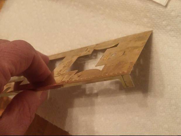
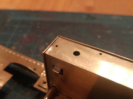
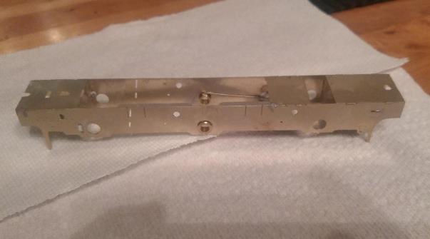
After cleaning the tarnish off the etches, I started from “step 1”, attaching the valences to the footplate. Here's the first piece soldered in place…
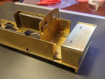
And from there, I've kept going. Somehow I found time to work on the kit 3 separate evenings over the course of a week (about 5 total hours). Here's where I am as of now:

The coal bunker isn't soldered in place yet. I also still have to add the beading at the top. The coal door handle needs to be added as well, but Jim says to solder that after the cab floor is in.
So, few things to ponder here:
1) Most of the other soldering has been from the “inside”, where the solder isn't visible except where it flows through the joint. (cab front windows and tank steps the exception, but those I tinned to solder in place…). I think i'll be able to solder the front (i.e. inside the cab) from underneath, as there are locating tabs that I can use there. But I'm not sure I can do the same with the locating tabs for the sides and rear, as the valences and rear buffer beam are almost overlapping those tabs, and I don't want to de-solder those by accident. Might have to solder from the “outside”, so there's going to be a lot of cleanup.
2) Wondering if it makes sense to fit and install the cab floor before I solder the bunker in place. Seems to me that it would make more sense, as then I can fiddle with the fit of both parts, rather than worry about folding the cab floor so it fits “just right”. I can also solder the coal door handle from inside the bunker before attaching it.
Anyone out there with experience on building this kit? Anyone have any insight on changing the “order of operations”
Davenport20954 - Mar 2, 2017 at 8:37 PM
Jim's Connoisseur models always go together easily and accurately to make a fine model. The instructions are second to none (from my small experience). If your kit is 15 years old the instructions may have been updated. If you go to the Connoisseur web site you can download new instructions for a LMS Jinty that include build instructions and clear photos of assembly. Stick with Jim's instructions and you won't go wrong.
Perhaps search the Gazette on line to find a build article for hints.
John Kneeshaw - Mar 2, 2017 at 8:44 PM
Well done for taking the plunge.
If you encounter an problem the forum population will help; and so will Jim if you phone him.
John K
Bob Alderman - Mar 2, 2017 at 10:45 PM
Don't worry about soldering the cab side from inside. Even if you manage to melt the solder holding the valence it will not come away as it is held in other places.
Bob
Bouch - Mar 3, 2017 at 2:50 PM
Hi folks,
Thanx for the input. I have already downloaded the new instructions, and several other helpful docs from Jim's site. Very helpful!
Bouch - Mar 3, 2017 at 3:44 PM
Next question. I'm figuring that those side tanks are a good place to add weight (same amount on each side, of course). The obvious question is: How much?
I haven't found any NMRA recommendations for loco weight, seems like they only have car weight standards.
I'm also figuring that this loco pulling a 15 car freight train would probably look about right. How long of a train could the prototype pull?
Jim Snowdon - Mar 3, 2017 at 4:31 PM
Mike,
Less than you might think. 12-15 wagons, especially on the flat, does not take an inordinate amount of tractive effort to pull and if you really want to add weight, a single thickness of lead sheet in behind the tank sides would probably me more than enough. Filling the boiler and spare space in the firebox, as some would do, would be overkill. On the principle that any weight in the tanks would be glued in afterwards, build the loco as is and see if it is heavy enough on its own, then add only as much weight as you find necessary to do the job.
Jim
DavidAtkinson4172 - Mar 3, 2017 at 4:48 PM
re Weight, I try and put enough weight in to allow it to pull what I want it to but to also allow the engine to slip a little without burning out the motor.
David A
Mike Evans - Mar 3, 2017 at 10:14 PM
If you want the loco to be the correct scale weight in relation the full size loco then I believe the formula is
(WT of full size loco in TONS multiplied by 2240) divided by 43 cubed
Therefore a loco weighing 100 TONS X 2240 =224000 and divided by 43 cubed =2.81 LBS
So if the finished model is weighed the appropriate weight can be added to make the scale weight.
Hope this helps
Mike
Raymond Walley - Mar 4, 2017 at 7:28 AM
The danger for ballasting with liquid lead us in using PVS to hold it together. In confined spaces it willeventually burst the container. See the 45xx build on my website.
Bouch - Mar 6, 2017 at 1:37 AM
Hi folks,
Here's what I've done…
I have a Dapol Terrier. It can pull 8-9 of my cars on a flat, but only about 5 up a 1 percent grade. (my “standard” weight for a van is about 150 grams) I weighted it, and its about 450 grams. So, by simple extrapolation, if I get my Jinty in the 900 gram to 1 kg range, then it should pull twice as many cars (may be a simplistic view…)
I also found a section of the guild manual (part 3, section 1.2.1), which states that an “average” tank engine would weigh 1500 grams, and the “average” 2 wheel van should weigh 200 grams empty, and 300 grams loaded. In section 1.7 (assuming I read it right), it estimates that to pull an average 40 car train, the loco would need to weigh 2.5 kg. So, somewhere around 1 kg should give me the ability to pull 15-18 of these “average” cars. As I said, my cars are lighter, for the most part, but seems like 1 kg is a good weight to shoot for, and shouldn't overwhelm the motor if the average tank engine weighs 1.5 kgs.
Then, I put a pile of stuff on the scale. The Jinty, as it sits now, the etches, the bags of castings, the motor, and the 3 packs of Slaters wheelsets. I figure this is a reasonable estimate as to what the finished loco would weigh. That came out at about 700 gm.
OK, Looks like I need to add 300 grams
I found that I could put 5 pieces of 1/16“ thick lead roof flashing, each piece 2” x 1“, into each tank and not interfere with the slots in the footplate to clear the tops of the drivers . I could also put 3 pieces of 1” x 1“ flashing under the cab floor, once again avoiding the corresponding slots. That much lead weighs about 175 grams. I was tempted to put some lead in the rear coal bunker, but as that's “outside” the wheelbase, I was afraid it would throw the balance of the loco off. (realizing that the cab floor is directly above the rear set of drivers, that's as far towards the rear as I wanted to go.)
I cut the pieces, and used 5 minute epoxy to glue them in place.
Once the Jinty is close to finished, I'll test to see how it performs, and add more weight in the boiler as necessary.
Thanx for the advice!
Unfortunately, I don't have any additional photos, yet. My 25W soldering iron seems to have given up the ghost after I got the cab floor in. I suddenly lost all heat, and no amount of keeping it plugged in changed anything. I need to get my multimeter out and try to figure out where/how a wire broke somewhere. My 80W is a bit large for what needs to get done next, so I need to do some work, or “retail therapy”. Once that's fixed, I'll be able to get more work done.
Bob Alderman - Mar 6, 2017 at 11:19 AM
I think you are going too heavy. I look out one of my Jinty's and weigh it. It's certainly run around the layout with at least 15 wagons behind and, not at the same time, 3 etched brass non corridor coaches with interiors.
Bob
Jim Snowdon - Mar 6, 2017 at 11:31 AM
Just to keep the two (if not three) sides of this topic in step, my response to Mike having posted the same text on the 7mm Yahoo group -
To put some perspective on your proposed locomotive weight, I have a GWR 72xx 2-8-2T, which is roughly twice the size of your Jinty (and in the full size, expected to deliver a bit over twice the tractive effort - 7F vs 3F). It weighs in at 1250g and will competently pull over twice your prospective load. At the same time, I weighed a selection of my rolling stock, and the average Parkside wagon comes it at 90-100g without any additional weight. I don't add weight to my wagons and haven't suffered any issues with running as a consequence. There is a school of thought that adding weight reduces derailments, especially when propelling, but in practice when derailments do occur it is usually a defect in the track that is to blame, sometimes no more than the wheel striking the end of the check rail in points as a result of the excessive lateral slop inherent in 32mm gauge.
I think you will discover that a single piece of lead sheet inside each tank will give you a much better starting point than will doubling the weight of the loco.
Regards,
Jim
Raymond Walley - Mar 6, 2017 at 4:17 PM
The most important thing to get right is the balance and making sure that the centre of gravity is in the right place. I have angines in which there is no room for ballast save in the ashpan but they still pull a prototypical load.
Bob Alderman - Mar 7, 2017 at 3:01 PM
Finally unearthed one of my Jinty's from winter hibernation…
It weighs 610 grammes or 1lb 5oz.
The motor is a Mashima 1833 with a 40:1 gearbox.
It has a sprung chassis whereby the the bearings in the hornblocks load cantilever steel springs that carry the weight of the loco, not per Slater's style that use the springs to encourage the bearing downwards from a fixed stop.
I easily handles around 15 wagons of various weights and has been seen at the head of three LMS corridor coaches from Sidelines kits.
As far as I can remember, without taking it apart, the additional weight has been added to the tank spaces.
The suspension was an experiment to compare with my other Jinty that is compensated. No real difference in pulling power but it runs much quieter as the body and motor are disconnected from the track by the springs. The knock the compensated one gives on crossing vee's is absent.
Your loco, I guess, has a rigid chassis. Provided it sits squarely on the track I would think at around the same weight will give the same performance.
Just reading back on Jim S's comments on weighting the weight of my loco would agree with what he says.
Bob
Bouch - Mar 8, 2017 at 7:01 PM
Hi folks,
Well, it looks like I may be coming in a bit heavy. Right now I estimate with the lead I've added its going to be 850-900 grams. Don't think that's too much, but I won't plan on adding any more until after I have a running chassis and can do “real world” testing.
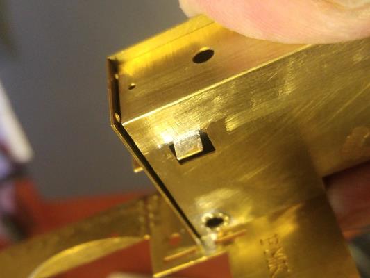
After adding the weight, I then attached the rear bunker and cab floor to the footplate. You can see the lead glued to the sides of the tank in this photo, the lead sheets stop just in front of the cutout for the sandbox fillers
Next was the inner side tanks. I followed Jim's directions, folded up the tabs which support the boiler and firebox, added the gland around the balancing pipe, and folded it up. When I test fit it, I found that the tank top had significant gaps at the front and against the cab front.
I don't have good luck flooding gaps with solder to fill them, and that's a pretty significant gap. I took some scrap etch, and soldered onto each end, filing away the excess. This did a pretty good job of filling the gaps
Here's how she sits now. The inner tank sides are just put in place, they're not permanently attached, Neither is the balancing pipe.

Note that the balancing pipe is a piece of 1/8” brass rod. (strangely enough, Jim didn't include this in the kit. Not an issue, as I had some, but I was surprised he didn't include it) I am concerned about the heat required to get solder to flow onto such a large piece…
Now for the question: According to this web site: \\http://www.cherryclan.com/2015/08/detail-modifications/ the boiler/firebox sits a little low. He shimmed it up .028. I'm pondering if I should do that as well. I realize that that means the smokebox will need shimming as well… If I do the shimming, I was to do it before attaching the inner tank side in place, as it should be easier.
Rusty - Mar 9, 2017 at 1:17 PM
I suppose I should explain this - as it was my build. It's not essential but I think it improves the look considerably even though it seems a small adjustment.
If you look at the full size loco the angle beading around the firebox virtually touches the bottom of the window bezels.
Fortunately there are plenty of Connoisseur build on t'internet so exhibit a: a standard build of the kit. There is a noticeable gap between the firebox angle and the window bezel.
By applying the small shim on the tabs it raises the boiler and firebox so that the relationship with the window bezels looks better - IMHO.

At the front end the shimming of the smoke box is hidden by the dummy frame etchings and casting in front of the smoke box. Personally I think it was worth the modification but it's not essential.
Adrian
Bouch - Mar 9, 2017 at 5:03 PM
Marvelous. Thanx for the explanation. Seems like a no-brainer to get it to look right in relation to the cab windows, and I hadn't noticed the discrepancy.
Bouch - Mar 9, 2017 at 5:15 PM
Thanx for the compliments. Soldering might not be as nice as you think, I spend a lot of time cleaning up where its visible…
I'm debating on compensation. I'm considering a few options.
1) Solid construction. Keep it simple. And on a loco with no pilot nor trailing wheels, all the weight will be on driven wheels no matter how many are in contact with the rail at any given time…
2) Compensation only on the center axle. Over on RMWeb, I see both “Jazz” and Sandy Harper use a technique where they enlarge the center axle hole vertically, and attach some piano wire to act as a spring. Seems a reasonable approach, but on this loco the center axle is driven, which complicates things.
3) “Springy Beam”. Seems the easiest method of “full compensation”, but still have to be careful with setting everything up. I have a set of Slaters hornblocks/bearings that I had purchased for a different project, but I could re-allocate those…
I realize there are proponents and detractors for each of these three…
Chapman16566 - Mar 9, 2017 at 6:31 PM
Rusty is quite right about the gap between the bottom of the window bezels and the firebox angle-iron. Derby GA drawing D29-11277 clearly shows the two actually touching.
Roger Chapman
Davenport20954 - Mar 9, 2017 at 8:03 PM
With the mass of weight largely over axels 2 and 3 perhaps just add some simple vertical tolerance to axle 1. Lots of ways to do this (even without hornblocks), so perhaps look a the Guild advice. The coupling rods are pivoted in the centre so it should be OK.
SimonD - Mar 10, 2017 at 2:24 PM
Bouch,
Sandy & Ken are experienced builders, with many fine locos under their collective belt, so following their footsteps will not take you into the wilderness, but…
If you spring the centre drivers of a 0-6-0, you will guarantee five wheels in contact with the track. You may be lucky most of the time, but you will lose contact on one of the fixed wheels from time to time, and it may be when the other ones on that side are on a bit of dirt/dead frog, whatever. It won't ever be as risky as an 0-4-0, and probably won't matter, but it's fairly easy to go for full compensation, which I would recommend.
Springy beam isn't really compensation, it's a sort of hybrid of compensation and springing. It has its proponents, and I will try it one day, as it may offer some real benefits, however for a first chassis, I would go for a conventional equalisation, using a rocking beam between the centres of the front & middle axle, and drive on the rear. Easy to do, well documented, and pretty much foolproof. If you have to drive the centre axle, there is an alternative which is marginally less simple, but probably better, using a central fulcrum on one end axle, and a pair of rocking beams to support the other two.
My first loco, built some 20 years ago, has a rigid chassis. It's a right pain, and needs fixing. On a rigid chassis you will only have one wheel on one side in contact with the track, and two on the other, at least some of the time (it depends how flexible the trackbed is, nothing is perfectly rigid). I would very much recommend that you don't do this, as it will be a frustration.
You will find a useful discussion about compensation on the ABC Gears website.
Hope this helps the thought process
Simon
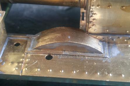
Bouch - Mar 14, 2017 at 5:26 PM
I diverged from the order of instructions a bit to build the firebox, to get the height correct (in relation to the cab front windows). Only took 2 hours to get 4 pieces soldered together…
After cleaning up the etches, I soldered the two front formers together, and then tacked them to the “top” of the firebox wrapper, careful to make sure the etched in centerlines matched. I used my radius gauge set against the rear former to determine the radius of the curves was 1/8“. Took a piece of 1/4” diameter rod and bent the curves around the front former. I used my mini-torch to try to anneal the brass where it needed to bend. I didn't want it incredibly soft, so I didn't get it quite hot enough, but it still bent easily enough.
If you're not familiar with radius gauges:

If you don't have one of these sets, they're very useful. My set is imperial, from 1/64“ to 1/2” radiuses, by 64th up to 9/32, by 32nd from there up to 1/2, but you can also get them in metric by 1/2mm increments. High quality sets aren't exactly cheap, but you can find a “budget” set for $25 or so, and for hobby purposes the cheap set is sufficient, IMHO. They're very nice to have!
Another great use for sets like this is then I can file the radius on the front edge of the firebox, and use the gauge to make sure its the same radius everywhere, even around the compound curve at the corners. To my eye, 1/32“ radius looks about right.
I then soldered the side of the wrapper to the front former, and then soldered in the rear former.
Here it is, test fit in the loco.

Now I can measure how low it is, and add appropriate shims to the supports on the inner tank sides. And then progress along with permanently attaching the tanks As with the tank tops, there's gaps. (the firebox is in the right location, as the etched holes in the tank tap and boiler for the tank straps are aligned, and if they're at an angle, it'll be obvious.) Need to add a little shimming to the rear of the firebox.
I put the pre-rolled boiler in place, and that looks too far back, as the etched line for the boiler band is right in line with the tank fronts, and photos show the rear edge should be right at the front edge of the tank. So this may need to be shimmed as well. Once the firebox is fit to location, I'll test fit that again. If I don't lose power today in the latest “snowmageddon” (expecting 12”-18“ of snow by tomorrow AM, Been snowing for 6 hours and about 5” on the ground already), I may get a lot more soldering done tonight.
Foster22336 - Mar 14, 2017 at 5:37 PM

SimonD - Mar 14, 2017 at 8:07 PM
Lovely looking loco, but please, PLEASE, colour the coupling hook - brass does not look nice here!
It looks like one of Bill Connell's. They're pretty accurate in side view, but I tend to taper the sides and front of the hook to try to get a more realistic appearance - the real things were forged and quite rounded. If you heat it till the links are red and drop in oil, that will nicely darken the links. The brass really needs some chemical black - Birchwood Casey is well known. Probably better to do the black before the oil.
Best
Simon
SimonD - Mar 15, 2017 at 6:49 PM
You would be quite within your rights to tell me to “sling me 'ook”, but I do reckon your loco will look better for the fix!
Best
Simon
Bouch - Mar 20, 2017 at 3:22 PM
Hi folks,
Did a little more work this weekend on the Jinty. I took some .025 thick brass shims and added them to the support brackets on the inner tank side. I cut them to close to the size of the support brackets, and tinned them.
Ran into a bit of a problem here. On the first one I did, I was pushing down on the shim when the heat got to the point of melting the solder, it also melted the solder I used to strengthen the fold. And the bracket bent down to about 30 degrees from the side, rather than the needed 90 degrees. When I went to straighten it, it of course snapped off…

I was a little more careful on the remaining, only breaking the one. I soldered 90 degree channel brass from inside the tank and re-attatched the support bracket. I then attached the inner tank sides to the footplate.
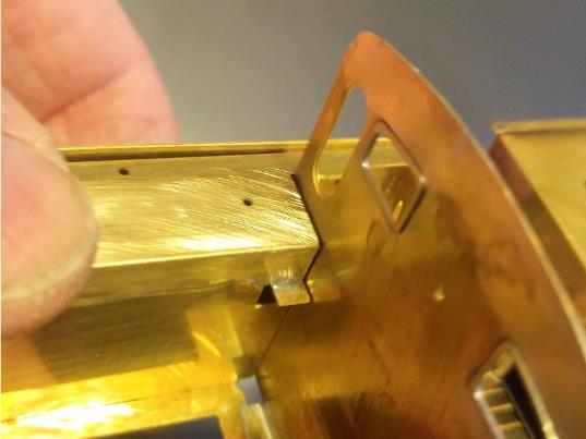
Next was the half-etched riveted beading to attach to the cab front. I tinned this, held it in place so its just about touching the cab windows, and soldered it in place. Since its higher than designed, this left a noticable gap where it meets the tank top.

Since its 1/2 etched, I couldn't use scrap etch to fill it. I had some .010 thick brass shim stock, so I cut small pieces to fit the gap, and soldered them in place. once cleaned up, you're really going to have to look to notice this..

I've also added some scrap etch to the rear of the firebox, to fill the gap mentioned in my earlier post. If you look carefully at the above photo, you can see the solder line where this shim was attached. With this shimming, test fitting the firebox and boiler shell, the boiler now sits in the correct place. Jim etched in slots where the boiler meets the tank ends, and everything looks good. Finally I added the beading at the top of the tank front/sides. Next step is cab rear and sides.
Bouch - Mar 25, 2017 at 7:08 PM
Hi folks,
Now that I have the boiler height straightened out, I started work on the cab rear and sides.
After installing the cab window trim rings, I needed to add the coal bars which protect the glass. These are made from brass wire, bent to fit. I made a small fixture from styrene to bend multiple pieces the exact same size, figuring that there would be 4 “small” ones (the outermost and innermost on both windows), 4 “medium” ones (next ones in) and 2 “large” ones (centers on both windows). Turns out, that wasn’t completely a correct assumption. The outermost on both were the same, but they weren’t the same size as the innermost. The 2nd in from the edge were close enough, as were the centers. So, I really needed 4 different lengths. Not a big deal.
Next was to get them installed so they were a consistent distance from the cab rear. For this, I took two pieces of scrap etch, put them against the cab rear. I then put the coal bars in place, and place a 3rd piece of scrap etch across them. Using wooden clamps, this made a “sandwich” which held everything tightly in place. A photo is worth 1000 words…

I soldered everything in place from the inside of the cab. After cleaning up, I tacked the cab rear in position on the rear bunker.

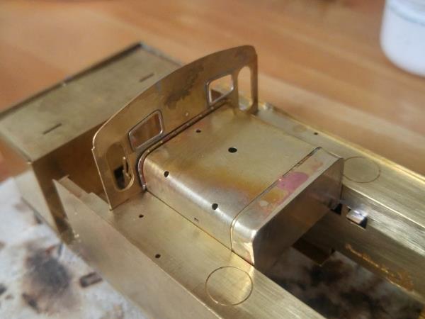
Now the fun starts… I took the cab sides, cleaned them up, and put them in position…

This doesn't look too bad. But…

And as they say in Massachusetts, “Light dawns on Marblehead” Clearly, the reason I had gaps between the tank sides (and firebox) was because, despite my best efforts to jig it up so it was square to the footplate, the cab front is at a slight angle, tilting towards the rear. It’s REALLY obvious in the 2nd photo above. I [B][I]should [/I][/B]have stopped and realized this earlier, since everything I've ever read about this kit was that it just about falls into place, everything fitting perfectly.
If this was a Gauge O Guild Gazette review of the kit, I think the appropriate statement would be “any shortcomings of the model are due to the inexperience of the builder, not the quality of the kit.” Another phrase which comes to mind is “experience is what you get when you don’t get the outcome you wanted.” Lesson learned to double check EVERYTHING and don't move on until you're sure everything's square.
Looking at it from the side…

It’s obvious that I shouldn’t just file it shorter, as then the front edge of the cab opening is too far forward. Looks like I have two choices…
1) Tear half the engine apart, get the cab front square, and reassemble, hoping I do it better the 2nd time.
2) Carefully cut the cab sides in half, remove the appropriate amount, file square, and solder back together.
Strongly leaning towards #2, as no one is going to measure the cab opening to find it 1-2mm short, and while it’s not trivial, it’s a lot less work than #1. Of course, that also means I'm going to have to shorten the casting for the roof as well. Still seems the better choice. I think while I ponder that (and repeatedly kick myself), I’ll work on the boiler. My club has a show next weekend, and I would rather display the body with the boiler at least test fit than have no boiler but the cab sides in place…
Davenport20954 - Mar 25, 2017 at 8:22 PM
I would guess everyone reading this will be able to recall a number of similar expletive moments during their time building kits. Filing down, patching in and gap filling solder all thankfully disappear behind that first coat of primer. And no one will ever know……..(unless they post it on a forum!)
Davenport20954 - Mar 26, 2017 at 12:25 AM
The vertical spectacle windows in this kit have an half etch recess on the outside and I wonder if this is for glazing. I enclose some pictures of a Jinty that seems to have had the windows temporarily removed but they do give an indication of the detail in that area.


If you get the chance always visit the real thing with a digital camera and you will find a wealth of details not seen on overall photos or kit instructions. The rear windows look a very neat job.
DLOS - Mar 26, 2017 at 10:35 AM
Yes, and that's where you start the slide down the slippery slope, just as I did! You begin to discover all the bits that are not in the kit, are wrong - or, at least not correct for your chosen prototype - and then you face the challenge of how to modify or to create them … At the end of the day, at that is only a metaphorical day because it becomes a very long time indeed, you have a splendid model that is much admired but I do wonder if you have enjoyed the build, and the subsequent running any more than the modeller who just followed the instructions and put the kit together in a mater of weeks (or even days). How do I know this? Hmmm.
I know that many will have seen this before but, from looking at the photographs, I saw that my Ixion Hudswell Clarke, which was to become GCR No. 278, needed to have jointed rods with marine bigends, rather than the version with overlapped plain bearing rods modelled by Ixion:

Before

After
Without the photographs I would not have known and I would not have taken on such a long journey. Still, I like long journeys, particularly if they are interesting.
Be warned ; -)
David
Bunker13521 - Mar 26, 2017 at 10:54 AM
Some interesting points raised in this thread…. in the first place, the sudden “oh no” second, when you realize that something doesn't fit, or you have put the thing together wrong… Should we perhaps have a section in this forum on how to put things right once they have gone wrong..? (How about calling it “Bodgers' Corner”? - I could fill it many times over with my own screw-ups and attempts at recovery…)
Also, the “who's going to know” question… I once had some loco photos lying on my desk at work, and when one of my colleagues asked what they were for, I said that I had to modify the model I was making because it was not in that state of rebuild for the livery that I wanted on the loco. She looked at me blankly and said “but who's going to know..?” To which I replied “well, I am going to know”… (She then reversed gingerly out of my office with a “why do I have to work with this lunatic..” expression on her face..) - But it is true - if you know it's wrong, you will never be happy.. Correct?
Bob Bunker - Hong Kong
Jim Snowdon - Mar 26, 2017 at 11:17 AM
The outer cab windows open inwards, with the glass held in a brass frame. The half etch surround is, I suspect, intended to represent that frame and isn't meant to be filled with anything.
Jim
Bob Alderman - Mar 26, 2017 at 12:19 PM
Looking back at your pictures where the gap is shown by the tank top and subsequent you have filled the gap with solder?
I think, with careful application of a small blowlamp flame, you will beable to locally melt the filling solder and a bit beyond and push the spectacle plate into the correct position. One side at a time.
Bob
paul copsey - Mar 26, 2017 at 12:29 PM
I have my own idea how to fix your cab problem but would think about moving that bracket inside the tank in front of the cab & then check the fit of the roof and see if it lines up with the corners. If it does then how hard is it to shunt the cab front forward on that front corner to line up with the cab side.
The other thing that probably wont line up if you bodge it is the boiler to the cab front , this is a case that a bodge here will have consequences further down the track .
Good luck
Paul
Bouch - Nov 15, 2017 at 4:53 PM
Hi folks,
After a long summer of not much modelling due to being outside, and a bit of discouragement due to my mistake on the Jinty, I've gotten off the schneid and started making progress again.
First was to take things apart and get the cab front right. I had to remove the tank top/inner sides and the beading on top of the tanks, and a few pieces on the inside of the cab. I carefully straightened the cab front, checking as best I could to make sure it became vertical. I had done quite a bit of shimmig of various pieces, and all those shims needed to be removed. I then put everything back together. The beading got bent to hell when I removed it, so that took quite a bit of work to get them straight and kink free. I also had to put new shims in different places, after filing things shorter in a few places (like the tank tops at the cab door). Took about 8 hours of work, but I got things back to where they should be. I then attached the cab sides.

Feeling much better about the build now.
Next, I decided to work on the boiler, knowing that I would have to shim the smokebox due to the raised boiler height. Few new experiences here, but nothing too troublesome.

I still need to install the washout plugs on the firebox, but I saved the whitemetal castings for last so I don't melt them while assembling other pieces.
In order to figure out the shimming for the boiler, I also installed the front splashers.

So, next steps are to install the washout plugs and get the boiler mounted. Hopefully by the end of the weekend I'll have most of the bodywork done. I'm also starting to ponder the chassis. The big question right now is if I'll use some form of compensation or leave it rigid. I know for an 0-6-0, the main benefit of compensation is for electrical pickup, but there's part of me that feels it needs something. I'm confident in my ability, having a decent machine shop and access to my father's excellent shop (He has 4 Bridgeport milling machines!)
Jim Snowdon - Nov 15, 2017 at 5:19 PM
The simplest approach is not to compensate the chassis but put all three axles in spring hornguides. The modifications to the frames are essentially the same, and it saves the need to make and fit the equalising beam(s) and/or rocking axle.
Jim
Bouch - Nov 16, 2017 at 5:54 PM
Last night I fit the washout plugs and put together the two pieces which make the frame extensions. No photos, but the boiler is just about ready to be soldered in place. I've done a few test fittings, and there's a small gap above one of the splashers which I need to fill.
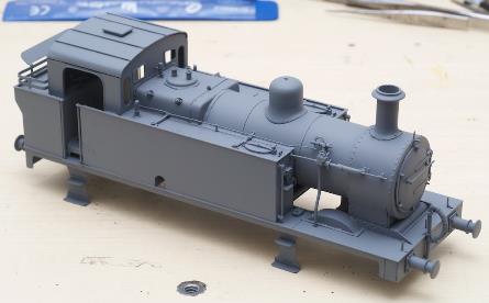
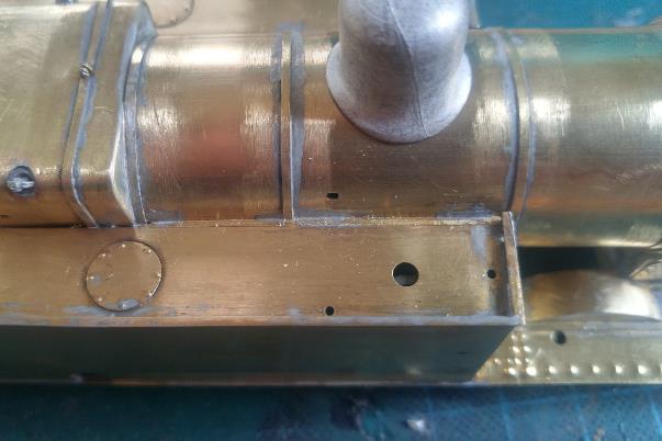
Bouch - Nov 27, 2017 at 4:22 PM
I've reached the first “major milestone” in this build. “Major body construction” is done. What's left on the body is all “detail parts”, do be done after the chassis is done and fitted to the body.


Note that the castings for the smokebox door, stack, dome, and cab roof aren't permanently attached, only thing holding them there is gravity.
Few interesting bits in the past week getting here. Around the front splashers there's trim pieces. The instructions say to file to fit. Well, when I put them in place they were quite oversized, about 2mm too long. So I cut them in half, soldered one half in place, then filed the other half shorter to get a good fit. I suspect that means I installed the splashers incorrectly, but I can't check that until I have the wheels in the chassis. Hopefully that won't mean the front wheel rubs on the inside of the splasher.

If you look at the 2nd photo you can see the joint (photos are more cruel that the naked eye), but once painted I'm sure it'll all but disappear.
Bending the coal bars was an exercise in patience. Bend it, check to see how far off it was, straighten a little and re-bend, repeat ad-nauseum. Probably took 20 minutes to get it satisfactory. But just when I thought the coal bars were fiddly, along came the “boiler infill” between the tanks and the boiler. Few things here.
1) It was designed to also fit between the firebox and the tanks. My firebox is a tight fit to the tanks, so that extension was simply cut off and discarded.
2) It was significantly oversized, I had to file about 1/2 of it away to get it to fit, in addition to filing small notches where the boiler bands are.
3) There's no support underneath, so if it twisted just a little, it would drop down between the boiler and tank.
4) The instructions didn't state how “recessed” this was supposed to be, and I couldn't find a photo either in my books or online. So, I “winged it” and recessed it about 1mm, so it doesn't look like an extension of the tank top, but it clearly fills in the gap between the boiler. At this point, I'm pretty certain that this is wrong, I'm since found a photo that shows it all but flush with the tops of the tanks. I'm not terribly concerned about this since the number of people on this side of the Atlantic that would a) know its wrong and b) notice is pretty low. (I'm also justifying this by thinking how many people have built this kit and don't notice the boiler height issue, which is quite obvious when you know where to look!). I may decide to take some scrap etch and fix this, but I'll worry about that when detailing the top of the tanks.
It took about an hour to file to fit, get it to sit flat in that small gap, and then solder in place.
One thing that seems to have developed, probably when I fixed the cab front, is there's a bit of a twist to the body. If one buffer beam sits flat, the other one has one corner about 1mm off the surface. You can see it if you look closely at the 3rd photo above. Not sure how I did that, as I had been checking along the way. While I'm annoyed about it, I'm not horribly concerned as long as I keep the chassis square. I can add small shims where the body and chassis meet to make sure that when I attach it I don't twist the chassis to match the twist in the body. But, its another thing I have to be more careful of on my next loco build. (spoiler: probably a “City of Truro” from David Andrews)
I gave it a good scrub with “Bar Keepers Friend” to remove much of the tarnish. To my surprise, this also affected the solder, it really “jumps” now where before it was a lot less visible.
I've been keeping track of how much work I've done on this, just for my own edification. Right now, including the 8 hours it took to fix the cab front issue, I've been at it for about 43 hours. Still a long way to go before I get to “Jazz speed”. :D
My club has a show this coming weekend, and I'll have this on display. Since the etch has a small plate to identify what it is, I took this and used it to make some “signage” as to what it is. Took some Humbrol crimson, painted in, and then sanded the extra off.

(once again, close up with the camera is cruel, it looks a lot better to the naked eye!) If anyone asks, I'll tell them that PMK is what Jim used to call his kits, I have a LMS brake from him that says that as well. I'll probably also bring the rest of the kit, so people can see the etches for the chassis. Next update we'll have started on the chassis. Lots to think about there, and also be a LOT more careful to not get things out of square.
Davenport20954 - Nov 30, 2017 at 10:50 PM
Some nicely detailed work completed; the window bar spacing in particular. I often use coffee stirrer sticks to space grab rails off the body; less chance of soldering the spacer in as well!
I was looking at the tank to boiler in-fill piece and wondered what went on at this point in the prototype. The boiler cladding and tanks are separate items (the cladding is removable) and so a gap presumably would not be inappropriate. In fact what looks like a tank bracing bar is a detail at this point, going through the cladding. (a second at the smoke box location).
Looking at the on-line Connoisseur Jinty instructions Jim seems to have left a gap at this point in his version.
I always use Bar Keepers Friend with a stiff paint brush for a clean up. Solder does react with some cleaners but a fibre glass brush (used in water) will put a shine back to any larger area. However, the dull solder surface should not worry a good etching primer; or primer of choice.
I envy those builders whose finished models seem to show no evidence of having been soldered at all.
David
DavidL - Nov 30, 2017 at 11:06 PM
One of the unusual features visible on these locos is the boiler band tightening cleats, which are located on the top of the boiler. (Well, I think they are unusual.) I think they should be visible on the model below. Laurie Griffin does them, in section 20 of his castings catalogue.
David

Bouch - Dec 5, 2017 at 4:29 PM
Hi David,
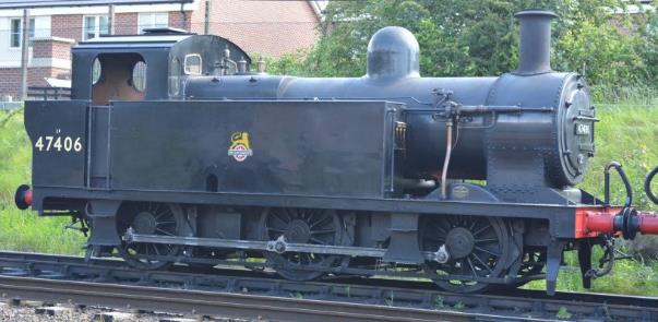
Interesting point. Since Jim included the cleat on top of the firebox, but not on the boiler, I assumed that they weren't visible on the boiler. Looking at my copy of Essery and Jenkinson's LMS locos Vol 4, most of the Jinty's pictured have them like on your model, the two between the dome and the firebox have them, the one between the dome and the stack doesn't. However, there were a few pictures where there were none on the boiler bands, only on top of the firebox. Looking online, it appears that several of the Jinty's in preservation don't have them on the boiler. I wonder if this was a difference among the various builders, or if it was that different sheds did things differently when it came to maintenance, or if later in life the bands were changed. I have found a great photo of 7298 which clearly shows the cleats on top of it. However, I believe that this was at the 1980 “Rainhill trails celebration”, so its during the preservation era. Since I'm strongly leaning on using this number (because of this photo!), I'll have to cobble something together to replicate the cleats.
BTW - the photo is available online at https://upload.wikimedia.org/wikipedia/commons/2/23/LMS_Jinty_0-6-0T_No_7298_at_Rainhill.jpg
Mike
DavidL - Dec 5, 2017 at 4:51 PM
Mike,
I [I]suspect[/I] that the reason for the cleats being on top on the 3 rear bands but not on the front one is that it is possible to fasten the front one from under the boiler, whereas the tanks get in the way for the other 3. Seems logical anyway.
Whilst recognising that using photos of preserved locos can lead one down the path of error, I thought you might find this photo of 47493, preserved at the Spa Valley Railway at Tunbridge Wells:

I have quite a few more if you are interested; I found them (and the one at the Great Central Railway) very useful when building my Connoisseur Jinty).
David
Bouch - Dec 6, 2017 at 11:35 PM
Hi folks,
I've started work on the chassis, but in a different order than Jim suggests in the instructions. He says to build the chassis up “solid”, with axle bearings in place, and then make the rods and make sure they fit. Many builds I've seen online build the rods first, and then make the chassis to fit the rods. That approach seems more reasonable to me, so I skipped ahead a few steps and started on the rods. (it also gives me more time to ponder compensation methods ;) ).
I've learned there's a LOT more work involved in making the rods than I thought. The rods for each side are made of of 10 etched parts and 1 piece of copper rod. 6 laminations for the body of the rods, and then 4 small overlay pieces to give the ends more thickness. The copper rod is to represent the joint where the rods would articulate in real life. On the model, its a dummy and the rod articulates on the crankpin of the center axle.
What I did was this:
1) Tin the surface on 4 of the laminations and all 4 overlays while still on the fret.
2) After cooling, cut them out, making sure to keep them organized so they get assembled in the right order. I didn't clean off the cusp that was left from etching, as I figured that would give me some room for error when stacking them. I did clean off the tabs where each piece was attached to the fret.
3) Take 2 drills that fit the holes in each “half” of the rod and mount them in holes on my soldering board. (I used #44 drills (.086) for the crankpin holes, #50 (.070) for the dummy joint hole). I made each “half” of the rod separately, so I wouldn't accidentally solder them together
4) Put the “inner two” of the laminations over the drills, and solder them together. (that is, the two pieces which would be closest to the wheels)
5) Put the 3rd lamination (the outer rod, which is fluted) over the other two and solder it on.
6) Put the 2 overlays over the ends and solder them on.
7) Repeat steps 4-6 for the other “half” of the rod.
(In hindsight, I probably should have put the fluted lamination down first, fluting against the soldering board. This would have made cleanup a little easier as I wouldn't have had any solder on the outer surface. I would have had to flip the rod on the fixture to install the overlays, but that's not hard.)
8) Clean up the cusp on the assembled rods
7) Add the copper rod in the appropriate location, overlength, and then file smooth on the back and a little proud of the rod on the front.
8) Tin the top and bottom surfaces of the rods, filling in the visible gaps between each lamination
9) Let it cool, then using a file and sanding stick, finish the tops and bottoms And, after that, I have the rods for 1 side of the loco. Only took almost 2 hours, if you include the cleanup time in step 9. I can't wait to build a loco with outside valve gear… :eek:
Here's what I have now.


(and I have absolutely no clue why the forum software flipped each of those images 180 degrees. They're upside-down compared to the copies on my computer, and I can't figure out how to rotate them…) For reference, that's a 2-56 screw in the 3rd photo, which is around an 8BA or M2 x .04 if I'm reading the charts correctly. The “end” on the center axle looks a little rough in the closeup photo of the joint, they look fine at normal viewing distance, so once they're mounted on the drivers they shouldn't be as obvious. I still have to clean up the holes, enlarging them to take the Slaters crankpins. I'll do that once both rods are done. Next step is the rods for the other side…
Jim Snowdon - Dec 7, 2017 at 12:22 AM
He isn't wrong if you are building a rigid, ie non-compensated or sprung, chassis, as then the axle spacing sets the rod dimensions and any tweaking that may be required. If you are going to build a chassis with hornguides of any description, the reverse applies, so you build the rods first (as you are doing) and set the hornguides (which have no other reference) to fit the rods.
Jim
DavidL - Dec 7, 2017 at 12:42 PM
I think Bouch's method is more logical (I suppose I would, as it's what I do myself). The logic says that if there is a mismatch between the holes in the frames and the holes in the coupling rods, one of them must be moved to match. It is[I] much[/I] better to move a hole in the frame a quarter mm or so without the move being visible, than to move one of the holes in a coupling rod. The human eye/brain are[I] exteremly[/I] sensitive to concentricity - a fact of which target shooters will be well aware - and the slightest eccentricity of a hole in such a small, visible area as a coupling rod boss will be noticeable. Moving a flanged bush a similar amount in a plain frame side, totally obscured by wheels, will be absolutely undetectable.
Bouch (do you have a forename? - it seems very formal to use a surname on here!), you have made a pretty good job of those coupling rods. Now I suggest you don't spoil the effect by fixing them on the wheels with a standard nut, get hold of some of the correctly modelled ones - I think it's CPL that do them. Also, a little lubrication cap on the bosses looks nice.
PS - I think you mean M2 x 0.4; 0.04 would be a mighty fine thread.
David
Jim Snowdon - Dec 7, 2017 at 1:10 PM
Not every railway used flanged crankpin nuts as modelled by CPL and others, eg LG; some used hexagon nuts, including Swindon when they built the D95xx locomotives.
Jim
DLOS - Dec 7, 2017 at 1:45 PM
Indeed. You beat me to it, Jim. Sometimes I use a 12BA half nut with two of the corners rounded off to represent the retainer. It's a matter of looking at the prototype and 'knocking up' something that is functional and passes for it in 7mm scale. David
DavidL - Dec 7, 2017 at 8:01 PM
Jim,
I'm sure you are correct - what I don't know about the GWR would fill a very large book indeed! However, it seems pretty clear that the LMS did, at least on the 3F tanks. Most of the photos in the Wild Swan Profile No 14 are too small to show them clearly, but several are just detailed enough to confirm this. Certainly the two preserved examples I have looked at do have them.
First, 47493, preserved at the Spa Valley Railway:
Those look original.
Second, 47406. preserved at the Great Central Railway:

I'm not altogether sure these are original but they are consistent with photos.
When I researched this area during the making of my own model, I was not aware of the CPL product, so I made my own:


I don't really recommend this unless you are well equipped and either (a) very hard up or (b) terminally masochistic!
David
Bouch - Dec 8, 2017 at 4:06 PM
Hi David,
You've pretty much described my thinking here. Easier to hide moving the hole in the frame than make an oval hole in the rods. And the 0.04 was definitely a typo.
For the record, my name is Mike Boucher.
Bouch - Jan 8, 2018 at 8:14 PM
On a brutally cold Saturday (high temperature was 7* F with 30 mph winds), I did a little more work on the Jinty.
First was to use taper reamers to open up the holes in the connecting rods to fit the Slaters top hat bearings. To aid with this, I used my gauge pins, measuring the hole size so I knew how much more I had to open it up to get to the right dimension.
If you're unfamiliar with gauge pins, its a set of precision ground pins which increase in diameter .001“ at a time.

This is a set of .062” to .250“. I also have from .250 to .500 (note: I got these 2nd hand, so there are a few I'm missing. I have enough for my current purposes, and if I need to fill a “gap” you can buy individual ones (but they're not cheap!)
I would use the reamer to open the hole a little from from each side, and then use the gauge pins to determine the current hole size. Repeat until I got close to the target dimension (.095”, measured using my micrometer, for reference), I would take smaller, lighter cuts. Eventually, I got the point where I could put the bearing in easily, but there was no horizontal play between the bearing and rods.

Several people have suggested that the original alignment rods I made are too long and will be unwieldy, and the tapers on the end aren't necessary. So, I made shorter ones with straight ends. These are 2.5“ long with 1/2” on each end turned to .095“. (I made 4, rejected one as I made a mistake and one side was .092”, fit was too sloppy) Still longer than the width of a chassis, but not by much.
with the rods on them…

We'll see which ones work better, or if I use both of them at different stages of the build.
And I started working on the chassis itself. I removed the sides and the spacers from the etches and cleaned up the kerf on the edges.
For the chassis sides, the rivets were pushed out, and I opened up the axle holes to fit the provided bearings. Once again, I used the gauge pins to constantly measure the hole size so I knew when to take lighter cuts. I was able to creep up so the bearing fits right up against the sides with no slop at all.

Next it to open up the center bearing hole for a little vertical movement. Pondering how I'm going to ensure there no horizontal play and the vertical play is consistent between the two sides.
Jim Snowdon - Jan 8, 2018 at 8:29 PM
If there's one thing about a steam locomotive, it's that it isn't a Swiss watch. There is tell of the day that when one of the munitions works, presumably Woolwich, built its first steam locomotive, there was embarrassment because it was way too stiff to function. They had built it to munitions tolerances, which were a good bit finer than railway ones. The slackness of some railways' tolerances, notably some of Gresley's, was a factor behind the “Gresley's knock” and the clanking which seemed a built in feature of the WD 2-8-0s.
I appreciate the quest for precision, but in practice, putting a 2.5mm drill through the rods will do perfectly well.
Jim
Bouch - Jan 12, 2018 at 2:26 AM
I'll try to bring the thread drift back under control by reporting on my latest work on the chassis…
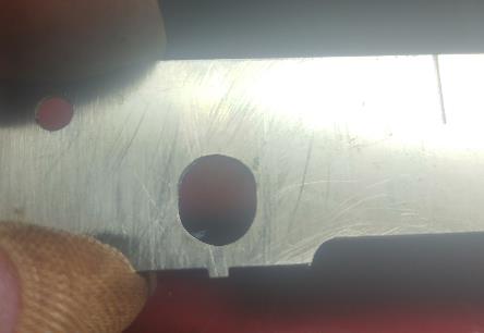
Tonight, I decided to file the center axle holes into a slot instead of a circle. I came up with a unique way to do it, I suspect, but it seemed to work for me.
First, was to mark the upper and lower limit of travel. I decided to extend the hole .032“ (.8 mm) in each direction. So, first step was to determine the dimension from the top of the frame to the bottom of the axle hole (The top of the frame is the only flat surface, so everything was done “upside down”, if that makes any sense.) The setup I used is probably easier to see than describe…

Now that you've seen it, let me explain a bit… My vernier height gauge it quite an antique, it was my father's from back when he was apprentice in the early 1960's, but it's what I've used for a LONG time, and I've never bothered to purchase a dial height gauge. The downside of it is that designed that the scribing edge can't go much lower than about an inch, so in order to scribe a line lower than that, you have to put a 1” ground steel bar under the part you're dealing with. (not to mention that I need my reading glasses AND optivisors to read it now). That's why the frame is sitting up off the surface plate. Secondly, to both hold the frame piece steady and make sure its vertical, I clamped it to a 123 block, which is sitting on top of another 123 block. Then I put a .266“ diameter gauge pin through the axle hole (smooth fit, but a .267” won't fit in the hole!) and the picture shows me measuring to the top of the pin. This finds the bottom of the axle hole. Remember, everything is upside down at this point! I read the height gauge, and did 2 equations. Current height + .032 (to get the “lower edge” of travel“) and Current height - .266 pin diameter - .032 (to get the “top edge” of travel) and scribed two lines at those dimensions.
I then held both frame pieces together, took 2 hardened machinists clamps and used the 123 blocks to make them square to the top edge of the frame, and pushed them right up against the gauge pin through the hole, and tightened them. I had them adjusted to maximize the clamping surface area, its easy to make only point contact with these, which would hold the frames together, but the would be prone to pivot on the clamp point, which isn't useful when you're counting on them to stay square.
Now I had both frame pieces together, with two “stops” on either side of the axle hole to make sure I couldn't make it any wider, only longer. And I put everything in a vise.

Then I took a deep breath to gain a little more courage, and used a 7/32” (.218“) diameter fine round file (intended to sharpen chain saw blades) to extend the axle hole in each direction to the scribed line. And I got two nice oval holes.

The “fixturing” may have been unorthodox, kludgy, unintentionally complex and convoluted, and possibly unneccesary, but it worked. When I put an axle bushings in the hole, they slide up and down, the full length of the slot, but there's no horizontal movement. Due to the angle of the camera, they may not look it, but they are both the same size. If you look through when they're held together, you can see this…
No going back now!
This weekend, we have a 3 day weekend here in the states to celebrate Dr. Martin Luther King, Jr. Hopefully I'll get some time in those 3 days to tack the frame pieces together.
Mike
DavidL - Jan 12, 2018 at 12:06 PM
Mike,
No, I would say most professionally done. A lot more precise than most people would have done, but no harm in that. I have often been guilty myself of over-engineering, and using more precision than was strictly called for, but the justification for that is that it is good to practise doing things as precisely as one can (well, within reason), so that when it really matters it becomes second nature.
On the problem of getting toolmakers' clamps to grip correctly, you are absolutely correct; it is important that they grip along the whole length of the jaws. The technique I find most effective is to slacken off the rear-end screw, tighten the one in the middle while holding the jaws flat on the work, and then tighten the rear screw as a final operation. Then try to give a waggle from side to side. If it moves, adjust and try again.
David
Bouch - Jan 14, 2018 at 2:41 AM
Hi Folks,
Now for a couple questions… One about the prototype, one about the center axle springy compensation
1) On the prototype, was it left-hand or right-hand leading? I found one video where it looks to me like its right-hand leading, but I can't tell for sure.
2) What diameter piano wire do people use for the “Jazz” compensation? I have some .015, but that seems too weak.
Thanx!
Bob Alderman - Jan 14, 2018 at 12:10 PM
Right hand leading.
Wire, no idea.
Bob
Bouch - Jan 14, 2018 at 2:08 PM
John beat me to the reply by a few minutes. “Jazz” is quite a prolific builder, hammers out a new engine every few weeks it seems. (most seem to be on commission)
His compensation method is to elongate the center axle hole, and use uses a piano wire pressing on the top of the axle bearing to provide springing on that axle. IIRC, Sandy Harper uses the same method. Seems reasonably simple, and I've had several people tell they've used the same approach with success. So, its what I'm 1/2 way through doing with my Jinty.
Here's a link with a photo showing the idea.
http://www.rmweb.co.uk/community/index.php?/topic/18405-bouchs-workbench-7mm-jinty/?p=2963386
What's the “real name” of this compensation method? I call it the “Jazz” method because he's the first person I saw using it, he uses it a lot, and I have no clue what its really called.
Bouch - Jan 18, 2018 at 4:29 PM
Well, I was going to work on the chassis itself over the weekend, but I didn't have the piano wire I needed. So, I decided to work on the wheels themselves.
First, Slaters wheelsets are notorious for coming out of the package rusty. Fortunately, mine weren't too bad, just a few spots (not bad considering I bought them about 15 years ago when I got the kit) but the axles were horrendous.
A quick spin in the lathe with a shot of WD-40 and some fine steel wool made short work of that.
Then, I sanded down the backs of the wheels themselves. But I noticed the “countersunk” hole for the crankpin is a) so big and b) off center to the crankpin itself?
Next, I put the threaded crankpins in. Connoisseur suggests countersinking a little to make sure the head is below the surface, but after doing the first one, I found it wasn't really necessary. On two of the wheels, I overtightened and seemed to strip the hole, even though I never felt any real resistance. The other 4, there was a definite “bottoming out” feel, so I'm not sure why the 2 that got stripped didn't have that feel to it. Jim also suggests filling the “countersink” with epoxy to lock the crankpin in, so I had been planning on doing that anyway, but with the 2 stripped wheels it seemed required. The screw is pretty well encased in epoxy.

So, with the wheels taken care of, I just had to test fit the rods. They might be a little tight, but its usually easier to loosen something up than it is to make something tighter.

The next photo was the obvious next step…

I've made the trip to the nearest hobby shop (30 minute drive), as it is on the way to my parents house (needed my father's Bridgeport mill for the stationary steam engine I'm working on) and I now have some .025” diameter piano wire, so I'm ready to work on the chassis itself. (a bundle of 5 pieces of piano wire, 3 feet long each, for under $2. I now have more than I'll ever use…)
Ian - Jan 21, 2018 at 10:33 AM
Bouch,
Sorry to pull you up but one should NEVER EVER use steel wool on a rotating piece in the lathe. If it catches up, very likely, on the chuck or the work piece then the damage it can do to your fingers is horrendous. The wool is very similar to fine swarf, razor sharp on the edges. I have seen far too many 'Accidents' of this type, it only takes a moment so be careful.
If you must polish the axles then fine wet & dry paper with a little oil is much safer and will polish the axle perfectly.
Ian.
Bob Alderman - Jan 21, 2018 at 1:58 PM
… and Slaters wheel no longer have the recess behind the crankpin.
Bob
Bouch - Jan 22, 2018 at 12:41 AM
Hi Ian,
Most of the time, I would agree with you, “normal” steel wool is way too coarse and sharp.
While I mentioned in my posting was that I used “fine steel wool”, I didn't say how fine. Its almost like a cotton ball made of steel. You can rub it between your thumb and your fingers to thin it out and not feel a thing. Just for fun, I just took a few strands and measured them with the micrometer. They were all around .003“ (.08mm) diameter. Great stuff for polishing.
Its just about impossible to cut yourself with this stuff.
Bob Alderman - Jan 22, 2018 at 12:25 PM
Yes it is! The strands can be pulled together into a string and that can be ripped through you fingers!
Bob
Ian - Jan 22, 2018 at 5:10 PM
Hi Bouch,
I’m sorry but you are taking a big risk. It may be fine and appear to be innocuous but it could form a string and seriously cut or even pull off a finger. I have seen the results of the latter but from a rag which caught in a chuck!
I see too from your later post a youngster in the picture so you are not setting a very good example for him!
Safety first.
Ian
Bouch - Jan 25, 2018 at 5:30 PM
Over the past few days, I've started to assemble the chassis of the Jinty. This is the part of building an etched locomotive which has me the most apprehensive, but its either move ahead or quit, so away we go…
First was to install the springing for the center axle. I used my Foredom tool to drill a .028” hole in the top of two of the bearings. I put them in the vise, and used a piece of scrap etch as a spacer to make sure the hole was the proper distance from the outer lip of the bearing. Then I took a short length of .025“ piano wire and bent one end 90 degrees. I then used a grind wheel in the Foredom to trim the bent end so it was shorter than the thickness of the bearing, so the wire wouldn't foul the axle. Then I put the bearing in the frame, put the wire in the hole, and clamped the wire to the frames where I thought was a reasonable tension. Using my 80W iron, and standard 60-40 solder, I attached the piano wire to the frame. I used the higher temp solder to reduce the chance I would accidentally un-solder it while assembling the frames.

Some pretty large blobs of solder there… ;) After taking the photo, I used the grind wheel in the Foredom to trim the end, so the wire doesn't extend any further than the solder point.
Next was to tack the frame spacers to one side.

Note that there's a 3rd frame spacer “D” which isn't tacked in place. This is because there's no 90 degree bend in it, so I left it out for now until tacking both halves together.
Now is where I go a little bonkers and over-engineer what needs to be done. When attaching the 2nd frame side to the spacers, I wanted to make sure that it was nice and square, so out came the machine shop tools… ;)
I have an 18” square steel surface plate, a nice large flat surface. On this, I placed four 1-2-3 blocks. Using the long alignment rods I made and described in an earlier post, I assembled the frame, including the axle bearings. I placed the rods on the 1-2-3 blocks, so all 3 axles would be perfectly level. Because of the springing on the center axle, I put a small piece of scrap there to weigh the frames down. I then put the side rods on the end of the alignment rods to maintain the spacing. Finally, I used a machinists square against the alignment rod and the frame side to make sure the axles were square to the frame sides.

Once I was satisfied everything was aligned correctly and square, I tacked the frame together in a few places. I then flipped the frame upside down and tacked in frame spacer “D”. (you can see “D” sitting on the top right 1-2-3 block in the above photo)
And now I have a frame. I was surprised at how rigid it is even with just a few tacks of solder in a few places

Next step is to tack the remaining 4 bearings in place and try to get the wheels rolling smoothly with the rods on. I suspect I'll have to do some fiddling there. Once I have a free rolling chassis, I'll finish the soldering of the frame spacers and make a nice solid frame.
Bob Alderman - Jan 25, 2018 at 8:42 PM
A suggestion. Next time do not put all the spacers on one frame side. Put one at the front on one and at the back on the other. Perhaps another each side too.
The danger of having all the spacers on one side is that the soldering heat will expand the second side alone resulting in a banana shaped chassis.
A left and right disposition will even out the heating.
Middle spacers can often be clipped in before soldering.
Bob
Bouch - Feb 1, 2018 at 2:34 AM
I had some time to install the axle bearings into the chassis, and the results are basically what I expected…
As suggested over on RMWeb, I didn't solder the bearings for the leading and trailing axles tight up against the chassis sides. I measured the difference between the witch of bearings tight against the fram and the back-to-back of the wheelsets, and found it to be about .058“ (1.5 mm) I used some .025” thick shim stock to hold the bearing out from the chassis and soldered them in place. I used the same setup I used when assembling the two halves of the frames to keep the bearings aligned.
I had some difficulty here initially, as I tried to use my 25W iron, as it was smaller and easier to maneuver. However, it didn't have enough power to heat up the bearings, so I got a cold joint on the first axle bearings. I didn't discover this until I took it out of the fixture. When I tried to use my 80W iron to just tack the other side, the whole bearing heated up and shifted out of alignment. I had to remove the bearing completely, clean up the excess solder on the bearing, and re-do it using the fixture and the 80W iron.
Here's a close up of the front axle, so you can see the spacing. The wheelsets still have a small amount of side to side play, but nothing significant, and the wheels spin smoothly in the bearings with the wheel backs not dragging on the bearing themselves.

Back to the fixture and I soldered in the rear axles, and now the drivers can be assembled in the chassis for the first time.

Now for the moment of truth, how well does it roll? there's tight spots at both front and rear dead centers on one side. I expected tight spots, as I've been building this to some pretty tight tolerances. As I've said, its a lot easier to loosen up tight spots than it is to make a loose chassis tighter. The first thing I looked at was if the axle bearings aren't quite right. I took the wheels out, and used the shorter axle alignment rods, and they're definitely tighter than the longer rods. It was hard to get the rods on between the center and rear axles. It looks like the long rods are good for making sure the chassis sides are square, but not so great for installing the bearings to the correct centers. (Jim and others correctly suggested this would be the case, which is why I spent the time to also make the shorter rods before getting to this point.) What I'll probably do on my next chassis is use the longer rods to ensure the bearings of one axle are perpendicular to the frame, and then the shorter ones to install the remaining bearings. With the shorter rods in place, I gave the rear axles bearings a quick shot of heat with my butane torch, which moved them just a small amount. Now the rods weren't as tight on the short rods, they're still snug, but its probably a thou or two between where they are now and for them to be loose. After reassembling the chassis/wheels/rods there's still a slight tight spot. At about 25 seconds into the video, you can see that once the body is put on the chassis, it rolls pretty well.
I might do some more tweaking of the holes in the rods, but I think its time to start working on the gearbox/motor. (and yes, I need to finish soldering the frame spacers in)
With the body resting on the chassis, I also tested the springing on the center axle. I took a dull X-Acto knife and put the blade on top of the rail. I slowly ran the loco over the blade, watching the center axle. When the front/rear wheels were lifted on the blade, the center axle stayed on the rail. Similarly, when the center axle was lifted on the blade, the other two axles stayed on the rail, no “rocking”. So, I'm satisfied with the compensation. While I suspect my club's layout, on its worst days, will have issues at the interface between modules, if the track is worse than this, we need to

One thing I have to start pondering is electrical pickup. The kit comes with some PC board and instructions on making phosphor bronze wire pickups. I also have a set of Slaters plunger pickups, and Jim has designed the chassis such that there are holes for these already in the frame sides, but I had some passenger cars with plunger pickups (for interior lighting) and they increased the drag on the cars “exponentially”. (with the plunger pickups , my Norfolk and Western “J” would spin its wheels pulling 5 cars. I removed the plungers, and it would pull 9 cars without any effort) However, the springs on the Slaters pickups seem pretty “weak”, so I don't think there will be a lot of drag. Which to use…
Bob Alderman - Feb 1, 2018 at 11:25 AM
If you do use the Slater's pick-ups and they are tight shorten the plunger not the spring.
Blunting the point will not increase friction and allows a little more freedom of movement on the spring.
Clean out the small hole in the plastic to stop the plunger binding too.
Bob
Jim Snowdon - Feb 1, 2018 at 12:24 PM
But, if you had put the blade under one of the leading or trailing drivers, the chassis would have rocked corner to corner.
What you have done is not wrong, but is limited to allowing the chassis to cope only with vertical irregulaties in the track. What it will not do is cope with any twist in the track, which occurs intentionally when the track is canted through curves (although this will be of only academic interest to most modellers as cant is not usually modelled), and unintentionally when our track is neither laid nor built to billiard table standards. For that, the solutions are either compensation or springing (preferably on all axles), or deeper flanges (although they will do nothing for keeping the treads in contact).
Jim
SimonD - Feb 1, 2018 at 12:47 PM
Good point, Bob,
if you shorten the spring, you will reduce the preload.
You will also make the spring stiffer, which you almost certainly do not want to do.
Shortening the plunger will reduce the preload without affecting the stiffness of the spring.
best
Simon
Bouch - Feb 1, 2018 at 4:22 PM
Quite true. I had a long internal debate about how I was going to compensate this engine. I decided on this approach as several well known, prolific builders use it, and it seemed like a reasonable easy way to add some compensation. When I get more comfortable with building running chassis, I might go for a full 3 point suspension.
Jim Snowdon - Feb 1, 2018 at 4:28 PM
When you are ready, I would suggest going for springing on all the axles as being the simpler option.
Jim
Raymond Walley - Feb 1, 2018 at 4:43 PM
Now there I would disagree with you Jim, beam compensation is easier to set up and very robust, a good start for a relative beginner and still my preferred method of compensation. Probably horses for courses though, when I finally get the River finished I'll find out if springing works properly for me.
Bouch - Feb 4, 2018 at 3:59 PM
Yesterday, while watching Arsenal eviscerate Everton, I did a little work on the side rods of the Jinty. As stated in my previous post, there were still some tight spots, so enlarged the holes in the rods to loosen it up. The rods has been reamed out to be a snug fit on the Slaters crank bearings, measured to be .095“. I had used my gauge pins to verify that dimension, the .095” pin would fit, the .096“ pin wouldn't. Using these gauge pins again, I slowly reamed out the rods, increasing the size of one hole one thou at a time, and then re-assemble the chassis and re-test. A lot more time-consuming that it sounds, took the full 90 minute match, and plus some.
At this point, most of the holes in the side rods are .097” diameter, with one or two reamed out to .098“. The chassis runs much more free now, especially when the body is on. There still one point where there's a very slight bind when there isn't any weight on the chassis, but I suspect that's because the center axles aren't at the same center line as the front and rear. As soon as a little weight gets added, the bind disappears. I think this is good enough.
Here's the latest video of testing the rods.
This is without any lubrication on the axles/rods, so its pretty free rolling. If I put the body on, as soon as I lift the track, it starts rolling. Time to finish soldering the chassis together and start working on the motor mount. Unfortunately, at some point I lost one of the small washers which go between the top hat crank bearing and the 12BA (?) nut. I'll have try to find a suitable replacement here in the states, I figure 0-80 or 1-72 will probably work, just need to find a source of washers that don't cost an arm and a leg, or come in boxes of 100…
DavidL - Feb 4, 2018 at 10:52 PM
I remember when I made my Jinty a few years ago, with fitted ball bearings, the chassis (with no motor connected) would spontaneously move to the point where the two coupling rods were at minimum position on dead level track. I know there is a wide variety of opinion about the merits of these bearings, but I was quite impressed by their effect.
David
Buckley10339 - Feb 5, 2018 at 11:36 AM
I allways fit ballraces to my locos.If i put hornblocks on the middle axle then its just the outer ones.One of the reasons apart from the smooth running is that as i tend to use the biggest motor i can in my locos it stops the brass bearings wearing out.In 20 odd years of using ball races i have never had to replace any, but three locos built without them have worn the brass ones out.
Pat.
Monday was a holiday here in the US (“Presidents Day”, when I was a kid it was “Washington's Birthday”, but now we celebrate all Presidents, including the doofus who holds the office right now). With plenty of time to work uninterrupted, I decided to try to build a gearbox and test the chassis with a motor. First, I spent another hour or so fiddling with the rods until there were no binds whatsoever. No more work with the gauge pins, only took a few twists of the reamer at a time and then reassemble and test. Next, I finished soldering the chassis together. It had just been tacked together, now its much more solid. Finally, I finished the motion bracket and soldered that in place.
So, with a nicely running chassis, time to think about the gearbox/motor mount.
First, as I expected, the provided motor mount is designed to be soldered to the sides of the chassis.

With the added springing on the center axle, using that was out. Over the past years, I acquired a few other options. First, a LONG time ago, when I bought the JM models kit for a new chassis for a Lima 4F (from Home of O Gauge, tells you how long ago it was!), I also purchased this gearbox along with a Sagami motor.

Second option, a plastic shell, double reduction gearbox from North West Short Line (aka NSWL - a well known US supplier of gears, wheelsets, and other drive parts.)

The NSWL gearbox has two issues. 1) there's no way to attach the motor directly to the gearbox. Many US models have the motor mounted on the chassis separate from the gearbox, with a rubber tube or some form of driveshaft connecting the motor and the gearbox. 2) The diameter of the hole in the 1st gear is significantly larger than the shaft on the motor, so I would need a sleeve somewhere along the line.
I wasn't terribly impressed with the HOG gearbox either.
1) There was supposed to be two triangular braces to solder on the inside, but the slots in the etches were about twice the width and significantly longer of the etch, all but useless.
2) The circular holes in the gearbox sides were etched oversize, the bearings flopped around.
3) The bearings themselves weren't usable straight out of the package, the hole for the axle was drilled undersize. The axles couldn't be inserted into the bearings, and it wasn't even close.
4) The holes to mount the motor were positioned such that the axle would block access to one of the screws. So, I had to tighten that before putting in the axle, which also limits being able to adjust the gear mesh.
But, I decided to go with the HOG gearbox since the issues seemed easier to deal with, so I soldered it up. I used a machinist square to verify the sides were square to the motor mount surface. Before soldering the axle bearings in place, I put them in the lathe and used a 3/16” reamer to open up the hole so the axles fit.

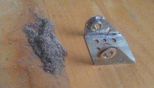
When I went to test fit it to the chassis, it wouldn't fit in the chassis. I didn't take a picture, but the width of the gearbox was significantly more than the distance between the axle bearings. Even if I hadn't added any compensation, it wouldn't fit between the bearings. To get it to fit, I took the axle bearings, put them in the lathe, and reduced the width to 1/8“ (taking about .045” off each). Then I filed down the outer lip of the bearings on the gearbox. Had to take quite a bit off there, as evidenced by the pile of filings on the work surface after I was done ;) If you compare the previous photo with this one, you can see the difference in bearing thickness.
It now fits in the chassis, no significant side-to-side play, but its not a tight fit either, slides in nicely.

After getting the chassis back together, time for a bench test. At first, there was a horrific bind, even with the gear on the axle not engaged. It took me a minute to figure out that I flipped the axle around during assembly, the wheel that was on the right when I was fitting the rods was now on the left. After fixing that, I was back to a free running chassis when the drive gear wasn't engaged. I'm a bit worried as to how much of a difference it made, so I have to mark the wheels so that doesn't happen again. Then I powered it up…
It sounds pretty horrific, although it does sound worse on the video than in real life. Its not quite “Coffee Grinder” loud, but its obviously not right either. Clearly I don't have the mesh correct for the gears. I fear that the gearbox isn't square, so the motor shaft isn't perpendicular to the axle, so the gears don't mesh correctly. This may be due to the axle bearings on the gearbox being such a loose fit, even with the sides square, the axle isn't. One other suspicion is that since this center axle has some side-to-side play, that once the motor starts spinning, it pushes the axle to one side or the other, which will force the gears out of mesh. To fix this, I would need to make the gearbox even thinner, and put a spacer in so the gearbox stays centered on the axle gear. I'm now understanding why people spend so much extra $$$ on precision made gearboxes.:D
But, at least it runs without binding. Note that as soon as the power is turned on, the wheels start to spin, that tells me that my controller doesn't really provide zero voltage when its at its lowest setting, but I'm also somewhat happy that the wheels start spinning with that little voltage.
I know that the motor is pointing towards the front of the chassis in this video. Its easy enough to rotate around to the correct orientation, but for this test, it doesn't matter which way the motor is aligned, and in this arrangement I can actually see the gear mesh. With the motor mount rotated so the motor is in the right position, I tried to test-fit the body on the chassis, and the motor might be too long. Its a Sagami 2240, which to my understanding means its 40mm long. According to the Connoisseur web site, Jim designs all his engines to take an 1833, 7mm shorter. I know the rear shaft of the motor is too long, it hits the firebox rear wall, so that would need to be shortened, but I'm worried there isn't a lot of room for the motor itself. And even if it does fit, I'm worried that the electrical connectors will be close enough to the body to cause a short. I need to do more test-fitting there.
But, since I have to take everything apart to add the chassis details, I'm not going to deal with this for now. Since I have a machine shop. I might make my own gearbox and throw out the folded-up one, but I'll ponder that, and the motor size, for a while. One other option is to order a reasonably priced 1833 gearbox from MSC, not sure I can justify the extra money for a helical gearbox.
So, the next step in construction is to put in the dummy inside motion provided with the kit. I also might go back and start adding details to the body.
Bob Alderman - Feb 20, 2018 at 5:09 PM
Etched motor/gearbox assembly. You may find this helpful next time: \\http://www.gauge0guildarchive.com/gazette_archive/Vol17-7/files/62.html
Bob
Davenport20954 - Feb 21, 2018 at 8:43 AM
I do not think it is unusual to have to reduce bearings a bit on the driven axle, as you have done, to get some gearboxes in place. Fit the bearings using a spare axle to ensure alignment then ream them in-situ. If funds allow (and geographical availability) have a look at manufacturers' like ABC Gearboxes and MSC as they do have some slim gearbox assemblies. My preference being to let the assembly float on the axle rather than solder it into the chassis. It allows you to change the drive unit if gear ratios seem inappropriate or things wear out.
David
DLOS - Feb 21, 2018 at 9:30 AM
Yes, this is a much better arrangement, David. It is essential if the driven axle is sprung or compensated but even on a fixed axle restraining the gearbox is 'redundancy' (in terms of statics) - the outer bearings could be omitted - and all the bearings need to be reamed and remain in line. David
Bouch - Mar 7, 2018 at 3:03 PM
But, last night I decided to spend a few hours with the Jinty again, just to work on something a little different. I assembled the dummy motion that comes with the kit. Doesn't look like much, but it took most of the evening. It'll look the part when the train is moving down the track…

Next step is the brake rigging. I suspect once this is added, installing the axles/wheels/rods is going to be a bit fiddly.
I've also found a Mashima 1833 motor and a set of 40-1 gears. I'm still pondering which direction I'm going with the gearbox.
Bouch - Mar 22, 2018 at 5:54 PM
Hi folks,
The next step on chassis construction is the brake hanger/blocks and rodding. Getting the brake hanger/blocks installed was fairly easy, layer the block overlays on the hanger, bend the hanger mounts, and solder everything to the chassis, being careful to keep the hangers loose on the .9mm wire.
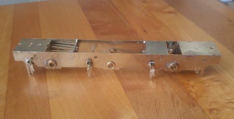

Next step is to solder the hangers in position. Few considerations:
1) Make sure that the brake blocks are far enough away from the wheel rim to prevent shorting.
2) Make sure they're a reasonable distance from the chassis, but still in line with the wheel rim. (that is, looking down from the top they should be far enough away from the flanges but not out beyond the edge of the wheel)
3) Make sure that the distance between each hanger is the correct distance apart so the brake pull rods all fit.
Due to consideration #3, I had to solder together the rear pull rod from 4 etches. The rod is two 1/2 etches (so they're full thickness), and the part which represents the crank is 4 etches thick. (and yes, I realize I didn't solder in the representation of the pin…)
I found getting everything aligned was a bit fiddly, since there were several parts which aren't soldered in place, and they needed to be aligned in several different axes. But, here's the first hanger soldered in position.

Note that the pull rod is not soldered in place yet. This is because I had a “wait, huh?” moment with regards to these pull rods. Looking down from the top of the chassis, here's what I figure will be a reasonable clearance between the wheel and the pull rod, about 1.5mm.

And the realization is that there's basically no way to have the brake pull rods soldered in place and still be able to install the wheelsets. I could do one side, slide the wheel in relative position, install the axle from the other side, and tighten the screw, but then theres not enough clearance to install the wheel on the other side.
So, obvious the question is…
Is there a trick to installing wheels behind the brake pull rods? Or should I just leave at least 1 side off and glue it on during “final assembly” after painting?
So, in order to keep moving, I soldered the 3 hangers in position on one side, with the pull rods just holding the relative position of the 3 hangers. Hopefully tonight I'll have time to do the other side.

One other question - The instructions show the rods for the top of the hangers going all the way across the chassis. Seems like I don't need the segment between the frames, and that can be cut away. Thoughts?
Bob Alderman - Mar 22, 2018 at 6:24 PM
You can fit the wheels with the brake pulls in place. A little bit of flexing will make some space. Only a little as you've already given yourself 1.5 mm.
If you do not want the top brake support crossing the chassis you can do them seperately. Cut a 15 mm length of wire, bend 5 mm through 90 degrees. Fit through the frame, short length inside. Turn the chassis on its side so the wire hangs down. Solder inside. If the chassis is supported level the wire should hang square to the chassis side.
I think it's too late on this loco, but the etched hanngers should support the brake even if you cut the wire now.
Bob
DavidL - Mar 22, 2018 at 10:08 PM
When I did mine, I thought it was a good idea to start with a single support wire going across the chassis, to get the alignment right. When soldered in place, you can cut off the internal bit.
David
DLOS - Mar 23, 2018 at 7:53 AM
It's probably not feasible now but, when I make mine, I arrange for the hangers to spring over their upper supports or for the upper supports to spring into holes in the frames. In this way, the brake gear may be fitted after all the wheels (but before the rods and motion) and it may relatively easily be removed again, if necessary.
David
Buckley10339 - Mar 23, 2018 at 8:57 AM
And one other way that i have just used on an 8 wheeled tender is to use 12ba csk bolts throgh the brake hanger from behind with a 12ba nut on spaced out to let the pullrod sit away from the wheel then to pullrod is slipped over the bolt and another nut tightened down on it.The excess thread is trimed of and filed smooth.Pullrods can be taken off and replaced at any stage for wheel removal.The bolts can be either superglued or soldered as required.The 12ba nut is kept in place with a tiny dab of superglue on the rear when in the correct place.
It uses a lot of nuts but its a fairly quick solution and its the first time i have done it but it wonnt be the last.
Pat.
Haines10259 - Mar 23, 2018 at 6:52 PM
Mr Boucher - I would seriously consider making the brake gear 'spring' into place as fiddling around with outside brake rods to fit wheels is ok once, but if you need to do it several times it becomes really irritating. Just assemble the gear in exactly the same way but don't solder the tops of the hanger assemblies to the pivot rods.
The other thing I would strongly advise is sticking some fag paper to the insides of the pull rods with araldite (or just smear with araldite but that gets a bit messy). That will prevent shorts even if the rods do touch the wheels. I do the same thing to brake shoes too. We spent a while on the Summit at St Neot's trying to lever brake shoes away from wheels and I don't like doing it on somebody's finished pride and joy! It is such a common source of bad running and it can be eliminated very easily at this stage.
Bouch - Apr 4, 2018 at 4:39 PM
Spent a little more time working on the Jinty chassis. In the end, I soldered the brake pull rods in place. Re-doing it to try to make them removable wasn't really feasable, as far as I could see. To try to use screws to hold the pull rods to the brake hangers would have required 00-90 at the largest, and I don't have anything that small kicking around (and they're not cheap!). We'll see how things go when I try to install the wheels.


With all the brass etchings attached to the chassis, it was time to start soldering on white metal castings. After tinning the chassis in the required places, I finished the brake gear by attaching the brake cylinder and the actuating rod.

Next step was to solder the sand valves (?) to the bottom of the sandboxes, and then the assemblies to the chassis. The castings are handed (that is, the one on the left side is a mirror image of the one on the right side), so careful attention had to be paid to make sure the sand valves were soldered in facing the correct direction.
Jim provided etched lines where they should be attached, but one set of lines was significantly more narrow than the box itself. The distance between the etched lines was equal, and the front box is clearly much larger than the rear. Looking at the pictures in the instructions, I aligned the edge closest to the center axle with the etched line, but I think I have it wrong as its VERY close to the front wheel. I'll have to unsolder and move it towards the rear.

I still need to attach the sand spout to the rear sandbox, but as that'll be a bit prone to breakage, I'll solder that in place once I'm done with the gearbox/pickup wiring. The only other parts left to be attached to the chassis are the 6 cast springs and then the pipes from the sandboxes to either side of the center axle (more parts prone to breakage, might hold off on those as well). Back to trying to get the gearbox running smoothly…
Bouch - Apr 4, 2018 at 5:13 PM
And now I figured out the problem with the sandboxes. I got them installed “backwards”. That is, the one that belongs in the front is installed in the rear. :mad::( I must've gotten myself disoriented between looking at the pictures, and having the frames upsidedown when I was soldering.
Looks like the chassis is getting dumped into some boiling water before the next workbench session…
Bouch - Apr 10, 2018 at 2:49 AM
Well, upon further careful inspection, I did get the sandboxes right. that is, the front box is attached to the front of the chassis, and same with the rear. However, upon further testing, I also found out that the front box isn't “very close”, its touching the wheel (before, I just eyeballed it, without having the wheel inside the brake pull, and it looked close. Once I tried to install a wheel, it was obvious that there was “foulage” going on.)
Looking at the (few) photos in the instructions, I have it in the right place. When I took the chassis and test fit it with the body, the hole in the footplate where the casting for the filler cap goes is aligned with the front edge of the sandbox. However, clearly its wrong, as the wheel won't fit. I dropped the front half of the chassis into some boiling water and the front sandboxes fell off.
I re-attached them, this time splitting the difference with the etched lines. That is, the center line of the sandbox is aligned with the centerline between the two etched lines. (or as close as I can get without measuring and scribing lines) There's now about 1.5mm clearance between the flange and the sandbox, but the hole for the filler cap is out past the edge of the sandbox. Any sand poured through that hole will be deposited on the ties. I considered moving the cap, but the hole is centered nicely between the front splasher and the tank front, which I have to believe is an accurate location (I can't find any detail photos of the prototype to confirm this)
Not sure if this is a failing of the kit, or of the builder, but it doesn't matter. If its the former, I have few options other than “leave it as it is and no one will notice” ;) If the latter, I can't see what I did incorrectly. I could move the sandbox again, towards the front by about 1 mm, but the hole still wouldn't align quite right, as the cap is more than 2mm diameter. It would be “less wrong”, but still wrong… I didn't take any photos, but I've also soldered the spring castings to the chassis. On to working on the gearbox.
Bouch - Apr 12, 2018 at 2:48 PM
Well, looks like I have the sandbox in the correct location. I was concerned because the hole to locate the sandbox filler cap on the footplate is further forward than the front edge of sandbox itself.
Someone over on RMWeb posted this drawing

So, it looks to me like the filler cap IS further forward than the sandbox itself. There's a spout, instead of the sand pouring directly into the sandbox.
On to working on the gearbox!
Bouch - May 5, 2018 at 10:28 PM
Been a while without any progress on the Jinty for a few reasons. But, time for a quick update…
I had hoped to get the motor/gearbox installed in time for the “Great British Train Show”, which was Last weekend in Brampton, Ontario, Canada. Didn't make it. The fold-up gearbox I made just isn't right, and the motor I had with it (a Mashima 2240) is physically too large to fit in the Jinty. But, I also have a Mashima 1833, so I thought I would fit the new motor and use all my model engineering stuff to figure out how/why things aren't right and get the axle perfectly square and the gear mesh right.
I didn't get far on that. While the motor mount has the appropriate screws for the 1833, the shafts on the 2240 and 1833 are different diameters. Which means the worm gear is too large for the 1833. I have a 2nd set of gears, and the worm on that one is the right size for the 1833, but they're a 40:1 reduction, so the axle gear is also smaller than my original. When I assembled the 1833, with the 40:1 worm and axle, they don't even come close to meshing, several mm gap between them. That's a long way of saying that everything I have won't work. Looks like I have a few options:
1) Design and build my own gearbox for the 1833 and 40:1 gears
2) Buy another fold up gearbox (with appropriate gears) made for the 1833
3) Buy a reasonably priced “precision” gearbox.
Heavily leaning towards #3. But, first I'm going to go back to working on detailing the body while my finances recover from a) purchasing a Minerva Pannier (on its way), and b) the road trip to Brampton.
I did bring the Jinty to display at the show. It was the first time I screwed the body to the chassis. Here's what it looked like:

(Need to get used to bringing a tripod and using a small F-stop for layout photos…)
While at the show (and subsequent travel days down to “Horseshoe Curve” in western Pennsylvania) , I didn't have much to do in the evenings. So, I brought a Parkside Dundas kit to work on once I got back from dinner. I usually make a rule to not start a new project/kit until I finish one, but I didn't have any 1/2 built stuff to work on, and these plastic kits are easy, small, and go together quickly. So, I made an exception to my rule. Here's what it looked like after the trip.
Got pretty close to finished. I couldn't glue on the brake levers until after I paint it, as the solebars are supposed to be the same color as the body. Once painted, just add buffers, couplings, some weight, and glue the roof on. Should be able to make short work of that.

Bouch - May 6, 2018 at 2:48 PM
I find consistency of weight is important. When you compare the weight to a similar length brass wagon, there's a significant difference. I usually add about 3 oz to a wagon this length, bringing it to around 5 oz. Another part of “consistency of weight” is that a wagon twice as long should weight twice as much.
You don't have to go by the NMRA weights (I think those are too heavy, a pound for an O scale 40' boxcar? just No), but I try to keep things reasonably close to each other. My rolling stock usually is about an “ounce-an-inch”, about 3/4 of the NMRA RP weight.
and the van got a coat of paint last night… Over here in the US, its often a challenge to match paint color. I used Tamiya acrylic XF-9 “Hull Red”, based on the photo on the box and a photo online of a preserved wagon at Bluebell. I think it came out a little too red, should be a deeper brown. Deciding if I should get a different paint or just claim the paint faded. ;) As if most people on this side of the Atlantic would notice anyway.
Bouch - May 29, 2018 at 8:51 PM
Hi folks,
Over the weekend I did a little more work on the Jinty. I'm working “from the top down” on adding details to the body. I've tinned the top of the boiler for the whitemetal castings, and added the details to the top of the tanks.

Next up is to finish the top of the boiler. Adding some scratch-built “clamps” for two of the boiler bands, and attaching the safetys/dome/stack. There is still one casting to add to the tank top, the water level indicator. I need to locate and drill a hole for that. Looks like it should be on the right tank, centered on the window so the driver can see it…
Davenport20954 - May 30, 2018 at 12:11 AM
For fitting chimneys and domes I simply solder a short length of brass studding (5BA screw) into the boiler crown and the same for the chimney (sometimes a bit of brass tube for a see-through chimney). The white metal fitting can be drilled and fettled as a slightly loose fit over the stud/tube. Final fitting is with a 5 min epoxy. This leaves a realistic open joint around the base of the fitting (they are removable in real life) and means you do not have to take a soldering iron to a white metal component; and avoid the grief that can sometimes be the result.
David


End of thread
