


Ace Products M&GN J93 0-6-0T kit
Prepared by: Tommy Day
Originator: John Hobden
See also John's video of this build
| Failed to open database: gaugegu1_gog2 | ret is false |
Jun 14, 2018#1
VigorousKingslynn
I posted on another thread that I had ordered a J93 kit from the new Ace website. I'm pleased to report that the Ace website now has correct pictures for each product shown but the online ordering system is not functioning. However, an email to the proprietor succeeded in getting a kit with my name on delivered to Doncaster and I have now had chance to open the box. For £179 I have some clean etches and a number of quality lost wax castings (by South Eastern Finecast I believe). I was told that the kit had been packed in a hurry and it turned out that some castings were missing e.g. buffers but then I was intending to substitute Slaters anyway so I wasn't worried. I have built ans Ace kit before and so I expect the odd problem. I am just a ham-fisted amateur and if I can build one anyone can. So I intend to document the process but don't wait up for updates as I have lots of Guild work to do before the 9.00 watershed when I start modelling. I have scratchbuilt one of these locos before,. actually my first O gauge loco and I made every mistake in the book. I also have a set of 1.5ins to the foot drawings of this loco drawn by a man who used to drive them so where could I go wrong?

My 1983 scratchbuilt loco has proved to be a very useful workhorse on my layout and other exhibition layouts. The origins of these locos were some Sharp Stewart 0-6-0s built in the 1870s for the Cornwall Minerals Railway. Some went to the Great Western Railway and were the inspiration for the 1361 class while others went to the Eastern and Midlands Railway in Norfolk. Their engineer, William Marriott, made a number of alterations including converting some to 2-4-0s with a tender but his best work was in rebuilding some into 0-6-0s in Midland style c1905 in the early years of the Midland and Great Northern Joint Railway which followed derby practice in locomotive matters. These locos were classified as rebuilds but in practice only the wheels and frames were used. So successful were they that one even survived to take a BR number.
So, let's look inside the box:

Looks good so far, clean and crisp etches in substantial thickness nickel silver.
Keep watching for updates.
John Hobden
Jun 14, 2018#2
Jim Snowdon
Is there any knowledge as to the provenance of the design, other than that it is recent enough to appear to have been drawn using CAD?
Jim
Jun 14, 2018#3
Tomlinson5811
There are three nicely-finished Ace M&GN locos. in the “Gallery” section (of the G0G website).
Jun 14, 2018#4
VigorousKingslynn
One of the locos in the gallery was constructed from the Ace J93 kit to S7 by the member who commissioned the kit from Ace. the kit is an original W. Ascough design but I don't know who did the artwork. I have found a couple of errors and hopefully solved them. More later.
John Hobden
Jun 14, 2018#5
Tomlinson5811
John Hobden
I was sure I'd seen the quote “developed with the assistance of the M&GN Society” somewhere.. but it's not in the Guild Trade News announcement, nor on the Ace website, so I don't know where? Incidentally, the price on the Ace website is £149 - what increased it to £179? Looking forward to progress with your build.
Jun 14, 2018#6
VigorousKingslynn
I think the price increase may be to do with putting lost wax castings in and the price in the Gazette ad is £179.99. The person who commissioned the kit is a member of the M&GN Circle whose drawings were used.
John Hobden
Jun 16, 2018#7
VigorousKingslynn
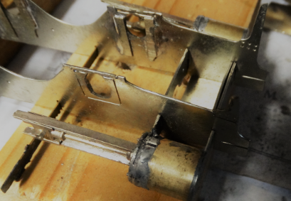
Chassis folded up and axle holes elongated for basic compensation. These will be reinforced with strips inside.

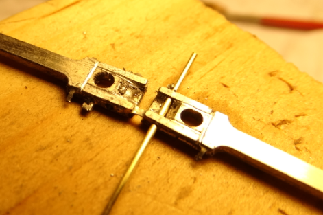
First problem encountered - the motion plate doesn't have the piece which joins the slidebars on these locos. With hindsight I could have added it from strip but I decided to fret out a replacement.

The larger than life picture shows all my filing marks where I tidied up the piercing saw work but illustrates the difference. Second problem: The fold-up system for attaching the cylinders was a good idea except that the cylinders would be too long and there was no way to get the part past the folded frame spacer. The cylinders were taken off the cross member and now fit neatly into the slots provided. I used brass tube instead of the cylinder wrappers supplied but that was just to make it easier for me.
Jun 16, 2018#8
Jim Snowdon
VigorousKingslynn said:
First, were the holes already elongated as etched, or is it a mod. on your part?
Second, you intend adding some strip inside the frames as reinforcement - what do you think the issue(s) would be if you didn't, ie built it as designed?
Neither are meant as criticisms, but I have always thought it important that if I am writing up a kit's construction and deviate from the way it is designed, I should explain why, as another builder might not want to do that, or needs to know why he ought to.
Is it known if that person did a test build and/or recommended any corrections before it went on general release as a kit?
Jim
Jun 16, 2018#9
Jim Snowdon
John,
Having now looked at some photographs of the J93s, I think the designer of the original motion plate has failed to take into account the much greater vertical sweep of the coupling rods. The prototype ones look quite different, with a much deeper sweep under the coupling rods.
Jim
Jun 16, 2018#10
VigorousKingslynn
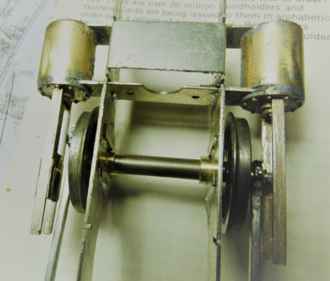
You are right Jim about the coupling rod sweep and I think I need to make greater allowance. It is a very short crankpin throw, so much so that I have had to countersink the crankpins so they don't foul the axle bushes. The holes as etched are simple circles with half etched lines to remove to accommodate Slaters hornblocks. I would never build a rigid chassis so it is just a case of choosing which system to use. Having built locos with sprung hornblocks, locos with compensating beams and with 3 leg suspension I have settled on the 3 leg system for this loco with the front and centre axles running in elongated slots. elongating the holes can introduce errors so the reinforcing strips are soldered into place with bushes in place and long 3/16 rods through to check distance and alignment. I'm not clear if the designer did a test build as well as the S7 builder but the mods suggested after the S7 build (including the motion plate) do not seem to have been carried out. So far slight irritations but nothing to really cry about. I have had to correct similar problems on other brands of kit.
John Hobden
Jun 17, 2018#11
VigorousKingslynn
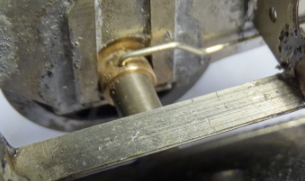
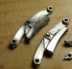
Cylinders and the rather nice lost wax slidebars assembled today (not cleaned up yet)
But now the perennial problem of limited clearance between rods and slidebars. This was discussed 5 years ago on the old forum with various solutions offered. I went back and looked at my 35 year old scratchbuild of the same loco and found I had thinned the crankpin bush down so the flange was almost zero. I then thinned the rod ends and the outer face of the bush. Finally I thinned the crankpin nut and, with no sideplay in the wheels everything cleared as it should. Must look up how the S7 builder overcame this with 1mm less clearance. Have things moved on in 35 years? Would Derek Mundy crankpins be better?
Wheels and rods fitted to determine the extent of the problem. This is not an issue with the kit, it is a perennial problem with outside cylinder locos.
John Hobden
Jun 18, 2018#12
Jim Snowdon
Are you saying that the cylinders as designed, ie the fold up arrangement, would have come out over length compared to the prototype, or that they would not have fitted the slots in the frame plates, or both?
I see now what you meant by the reinforcement strips inside the frames either side of the axle bearings. What I don't see is anything to prevent their rotating with the axles, or is that something to follow in due course?
Jim
Jun 18, 2018#13
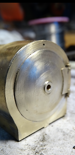
Sandy Harper
Would Derek Mundy crankpins be better?
From what I can see in your photograph John, I doubt it although you might be able to save about a millimeter each side using them without modification.
The only reliable method I have found, of resolving the front wheel crank pin issue, is to use the Slaters crank pin bearing in reverse and do without the nut and washer on the outside, but, that needs the builder to upgrade the Slaters 12 BA crank pin, cheese head bolt, to a 10 BA, countersunk bolt, and to cut a 10 BA thread in the original crank pin bearing, so that it can be screwed directly on to the crank pin, in reverse, with the 'top hat' flange on the outside acting as both washer and nut, instead of against the face of the wheel as normal. The hole for the crank pin in the Slaters wheel will also benefit from taping 12BA.
A 10BA washer should also be placed between the wheel face and the rod to maintain the clearance from the wheel. That should resolve most clearance issues but you can further increase clearance by thinning the coupling rod boss so that the 'top hat' of the bearing is recessed and flush with the outside of the rod. If you don't want to replace the 12BA pin with a 10 BA pin you could turn up a new bearing , threaded 12BA, but that would probably need the use of a lathe, or know someone who has!
The above is the 'hand tool' option but I'm sure others could come up with a more elegant 'engineering' solution using machine tools.
Regards
Sandy
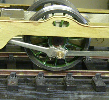
PS I found these photographs of my Skye Bogie where the clearance was needed between the crank pin and the footplate valance. Same difference!


Jun 18, 2018#16
DLOS
I am confident that you will not have a problem if you use some or all the techniques available in your armoury to address this:
Remove all but the merest hint of end-float on the leading axle by packing out between wheels and frames with spacers (washers)
Retain the coupling rod on the leading crankpin with a reversed and tapped top hat bush, as Sandy described. I make my own, retaining the 12BA screws [Note: I have never come across 10BA or 12BA bolts] and drilling two holes in the brim of the hat to tighten up the bush using a peg spanner*, but carefully filing on flats until a conventional spanner will fit snugly is a perfectly acceptable alternative
Counterbore the outer laminate to allow the brim of the hat to sit down in it (leave sufficient protruding if you have filed on flats; one of the advantages of the two holes method is that the brim may be made flush with the face of the rod); this much is easier done before the laminates are assembled
Ensure that the gudgeon pin screws head do not protrude beyond the back of the crosshead castings, which may also be thinned in extremis
I hope this helps and do let us know how you get on.
David
Jun 18, 2018#17
Turnbull21603

These items are S7 specific. I use them for building Broad Gauge locomotives. You will note from the photograph that the wheels are specifically made up with a threaded boss to accept the crankpins.
The method is very similar to the solutions proffered by both Sandy and David. However in S7 there is no need for any modifications as they will automatically increase the clearance.
Les
Jun 18, 2018#26
VigorousKingslynn
To answer Jim first, the fold-up cylinder saddle would have made the cylinders too long but the slots are etched at the correct distance apart so the separated cylinder ends fit correctly.
When I have previously used elongated slots there has been a spring wire attached to the bushes but I was not intending to do that this time so I may have to solder on a retaining wire. I may have some oversize bushes that I could file flats onto. I should think ahead more!
Onto the crankpins, the S7 builder turned replacements and tapped them. All the suggestions have given food for thought and the idea of tapping a reversed crankpin bush is attractive. I don't have a 10 or 12BA tap but could get a friend to do it.
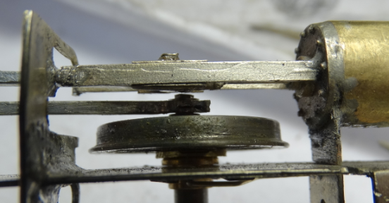
I looked again at my scratchbuilt loco and can see how simple that system is so may just do it again
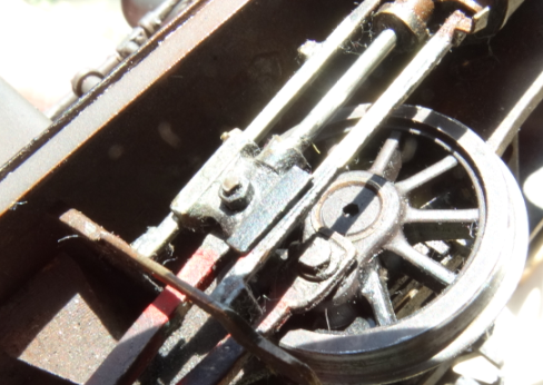
I fabricated that crosshead and fretted/filed the rods from solid brass!
Look how thin I made the slidebars - that probably helped with clearance. There is no sideplay in the leading axle. The thin end of the rod looks awful from below but you can't see it from above or the side.
John Hobden
Jun 18, 2018#27
Buckley10339
John,Gladiator do sets of crankpin bushes tapped 10ba i have used them with success.They are identical to Slaters you just put them on the other way round with a ba washer (cannt remember what size maybe 6/8 ba) on behind the con rod to keep it from hitting the wheel retaining screw and tighten up.I believe that some who use them file flats to use a spanner or slots to use a oo wheel screw key.I carefull tightened them with mini pliars .
Pat.
Jun 18, 2018#29
Sandy Harper
John
A small hole, 0.8mm, drilled into the bearing with an L shaped length of 0.7mm steel wire inserted, and the other end soldered to the inside of the chassis, will serve to stop the bearing rotating and provide a gentle spring to the bearing.

Regards
Sandy
Jun 18, 2018#32
Jim Snowdon
Assuming that you locate one, if you attempt to tap the Slaters bushes as they come, the tap is a very tight fit. If you want to reduce the risk, it is worth opening the hole up to the proper tapping size. You will also find that a proper pin chuck (not a pin vice) will come in handy for holding the bush, whilst a good way to hold the tap is to put the square in a pin vice and use that to turn it. I find that way to be more sensitive and easier in the hand than having the tap in a conventional tap wrench.
Jim
Jun 18, 2018#33
VigorousKingslynn
You engineers assume everyone has a lathe and a full range of tools. (Elitist?)
I have never needed a 10BA tap before though I use my 8BA ones a lot. Remember also that many of our new recruits purchasing RTR may have little more than a screwdriver.
John Hobden
Jun 19, 2018#35
MrGladiator
At the risk of running foul of forum rules I can advise that Gladiator will provide 10BA tapped bushes but are presently out of stock. New stock has been ordered of two types. One with a round head and another with a hex 8BA form that can be easily screwed in place.
David
Jun 19, 2018#40
VigorousKingslynn
I have two offers of loan of taps from my local group (where would we be without friends?) and will try the Slaters bushes reversed and tapped first for simplicity. Looking at those turned by DLOS I can see getting the pegs and holes accurately lined up would be a problem but if I file some small flats on the outside they will tighten with a spanner or pliers. The end of the screw can then be filed off and it should look like the prototype as does Sandy's Skye bogie.
John Hobden
Jul 5, 2018#46
VigorousKingslynn
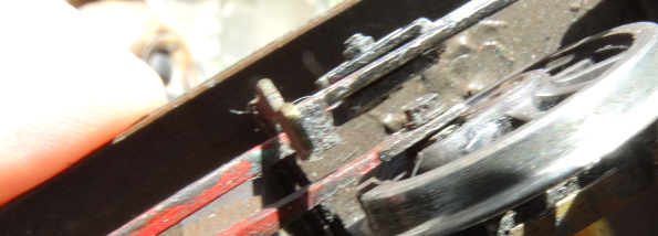
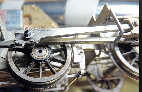
After a busy couiple of weeks on Guild stuff I managed to pick up the model again this week. First I installed spring wire as suggested by Sandy the set about getting the motion plate and slidebars sorted.
The nickel strip going diagonally across the picture has a rod underneath which acts as the rocker for the three point suspension. The clearance issue between the crosshead/slidebars and the rods has been solved. I used the same thin nut solution as I did in 1983 and moved the slidebars out a bit as well.
You can probably see that I cut out the part of the motion plate that went under the rods on the prototype, mainly because it was going to be a pain every time the wheels came off.
Then came disaster! I was trimming the slidebar ends with a slitting disc in the mini drill when one of them snapped off at the cylinder end. The solution was to drill into the loose slidebar and insert a pin through into the cylinder. It worked!
Representations of the lubricators added from brass rod and then I was ready for the rods
Jul 6, 2018#47
Jim Snowdon
But also, to judge by the earlier pictures, because the slot in the etching was far from deep enough to accommodate the full sweep of the coupling rods so would never have worked without modification. The shape of the motion plate is one of the distinctive features of these locomotives that, if the builder wanted to reproduce correctly, would necessitate replacing the kit example with one cut from scratch.
Jim
ps. I can understand why you modified yours the way you did, and am not criticising that, only the poor design of the kit.
Jul 10, 2018#48
VigorousKingslynn
A quiet weekend allowed some time on the J93. The phone was quiet as everyone was watching the footie. Good result for England and the breweries.
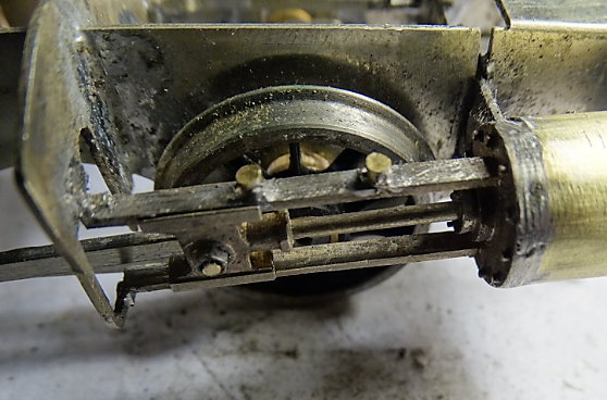
So, a lot of filing later the sandwich big ends are looking OK. There was a simulation of the cotters on the etch but not enough meat so I drilled through and made some from brass wire.
A bit of adjustment to the slidebars and motion plate and on to the brakes. The etched brakes are quite clean and soldering them together was quite therapeutic. I soldered the shoes to the hangers with HT solder and everything else with 188.
I can adjust the brake shoe position later if need be once I have checked all clearances. Next I must fit pickups and test run. I could push it along with a finger before I soldered the motion plate but it now has a slight bind. Must investigate why.
Jul 12, 2018#49
VigorousKingslynn
Started on the body now. The footplate comes as two layers with the upper one being half etched to locate the lower one which has the valences. The half etched fold lines for the valences have relieving slots which would show if there were no valence overlays. It all fitted well and has slots ready for tabs on the body parts.

I decided to fit the bunker next but it is 1mm too short at the sides while the tank sides are 2mm too long at the sides. The problem with this is that it puts the cab rear too close to the back of the loco. I got over this by shortening the shelf that the cab rear rests on so it now looks right. The tank sides and front had also been drawn to match the smokebox rather than the boiler so I made fresh ones - didn't take long. The cab rear was fitted next and then the bunker beading. This is an accurate etch and cleverly interlocks with the cab sides as does the tank top beading. The beading has a very delicate hole in it to match the cab handrail stanchions but there is no hole in the footplate. The cab front locates correctly in the slots on the footplate. There are some finely etched spectacle plates and i remembered to punch out the rivets for them before soldering in the cab front but I forgot to do the rear!
All construction must now stop till the missing boiler arrives.

Jul 13, 2018#53
VigorousKingslynn

M&GNR Class MR 0-6-0T: Built from the test etches for a kit by Ace Products by E R W Clark and shown on a S7G layout. Paint job by David Studley, photo by Eldred Clark.
Jul 13, 2018#57
VigorousKingslynn
I don't know who drew the artwork but where it is correct it fits well and some of the detail is very fine. It just seems careless and there is no sign of the test build notes having been taken note of. It is buildable if you check everything against the drawing (always a good idea) but even though it is a simple loco it is not a beginners kit. I am still enjoying building it.
John Hobden
Jul 13, 2018#60
ChrisSimpson
John, you haven't mentioned that there could be a video of the build shortly. For other members John has provided me with video footage to date. I eagerly await the completion.
Chris
Jul 29, 2018#64
VigorousKingslynn
I got back from holiday to find the missing parts had been dispatched from Ace. The boiler was already rolled and the castings look OK (note the shiny brass which seems a bit softer than the usual hard variety you get with lost wax). It should be easier to fettle.

John Hobden
Aug 1, 2018#65
VigorousKingslynn
Boiler and smokebox now progressing. the single smokebox overlay was not thick enough and the second one had half etched rivets which would be difficult to solder to so I made up my own wrapper and sweated it on, followed by the outer one with the half etched ring. I now had the correct profile between smokebox and boiler and the front matched the smokebox front which was accurate according to the drawing.
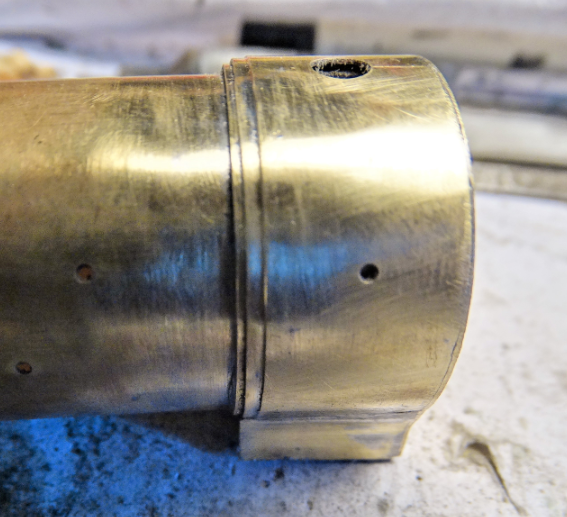
I decided to fit the lost wax smokebox door next - but, as they say in the documentaries 'there's a problem'. The smokebox front has a small hole in it but the door has a recess about 3mm in from the edge so the door would not sit flush as is characteristic of Johnson type doors. I started off filing off the surplus but it is difficult to hold flat, the brass is hard and when you file something like this you inevitably stray and take material off the edges which you want to preserve. So I decided to open out the hole, starting with a rough hole cut with a slitting disc and finishing off with a large coarse burr in the pillar drill. A bit of fettling and I had a good fit. I tinned both the front and the door with 100 degree solder, scraped off the high spots and soldered on using the soldering station at about 200 degrees. Then I realised I have to solder a lamp iron and handrail knob to the top of the smokebox. Think ahead!

The problem and the solution. The boiler/smokebox unit is separate and will remain so until after painting. The tab below the smokebox clicks perfectly into place in the slot provided and the fit at the cab end is the same so it would fit without any glue or solder.
John Hobden
Aug 1, 2018#66
DLOS
Oh for a lathe - with that great lug on the back of the door: hold the lug in the chuck, machine away the protrusion (with a left-handed tool) - in fact, make a depression, leaving just a narrow raised rim - and you're there. However, without a lathe, I would have tackled it in the same sort of way you did, John, although I'd probably have marked out the hole (using odd-legs) and cut out the ring with a coping saw.
David
Aug 1, 2018#67
VigorousKingslynn
If I hadn't already soldered the smokebox front on I would have used the piercing saw.
JH
Oct 4, 2018#69
VigorousKingslynn
I bet you thought I had given up with the J93 what with it being an Ace kit and all that. Well actually, once the basic body was together it was plain sailing. Then Guild work intervened and it was several weeks before i could finish it. All the small parts fitted well and it received its primer the Wednesday before I set off to start laying out Guildex on the Thursday. on my way over i got the preferred colour of cellulose mixed in a rattle can by Jawell Paints in Coventry to be sprayed on my return. The began the long process of lining. Day 1: horizontal yellow lines. Day 2 vertical yellow lines Day 3 curved yellow lines Dat 4 horizontal black lines etc etc then the other side and each end. I left handrails, ejector, safety valves and lubricators off till after painting when I had united the boiler with the footplate. So accurate was the fit that it just clicked into place and i have neither screwed, soldered nor glued it.
Now the bad news: After painting the re-assembled chassis runs like a jack rabbit - but then so did the scratch built one 35 years ago so I am hoping some fettling will cure that.

John Hobden
Oct 4, 2018#70
John Kneeshaw
Silk purses and the auditory organs of female porcines come to mind
John K
Oct 4, 2018#71
Jim Snowdon
Very good, John, and as someone might once have said, a good coat of paint can hide a thousand sins.
Having seen the issues that emerged during the earlier stages, how would you rate it as a kit - suitable for a beginner/suitable for someone with modeest expertise or requires considerable expertise?
Jim
Oct 5, 2018#72
VigorousKingslynn
It is definitely not a kit for a beginner though such a simple loco could have been designed as such. Even the outside cylinders could have been made easy to construct with minor changes to the design. Some of the design ideas are very good but there are careless errors in the chassis design and easily avoided smaller errors in the body. The detailed advice given by the test builder has generally not been incorporated in the production examples but then it was a model commissioned by an individual and probably not going to sell in commercial quantities so commercial pressures come into it. It is buildable by someone with average skills provided they know a bit about kit building and are prepared to look for problems in advance of each stage.
John Hobden
Oct 5, 2018#74
Jim Snowdon
Thank you, John for a concise and accurate summary of this kit.
Have you thought about putting a link to this thread in the Reviews section of the forum (as the place prospective purchasers are likely to look first)?
Jim
