Table of Contents
CONVERTING TOBY
By Bob Savage. Pictures by the author.
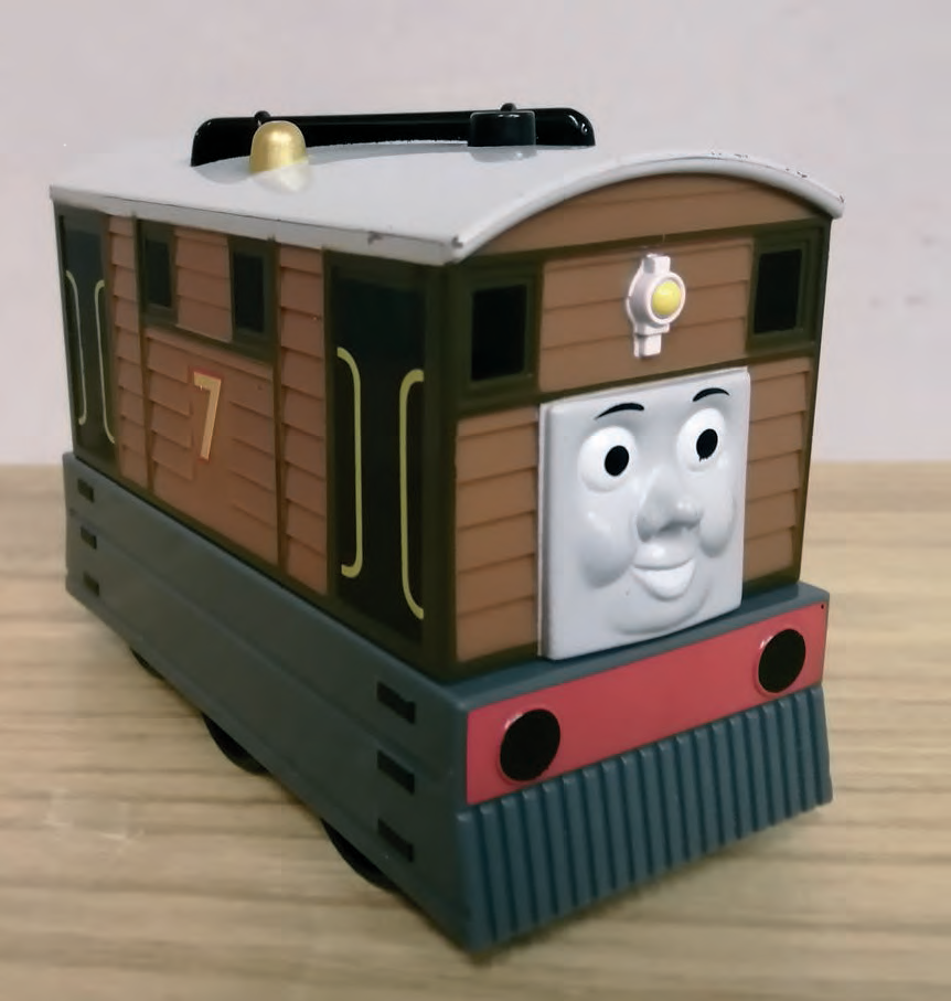
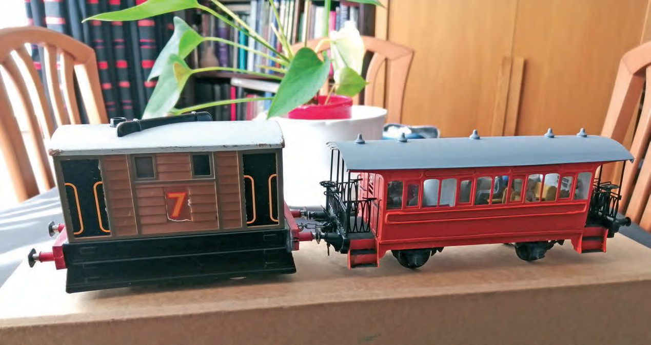
WELL THIS MAY BE ON THE DARK SIDE for some, for others it will be light. This toy has been available in a lot of supermarkets over the last few years at around £15.00; now to be found as a cast off in a charity shop £1.00 - £5.00. So a big expenditure is averted. I have made a power bogie underneath to run on O gauge, mostly from the scrap box. The two supporting coaches are from a D&S kit, which includes a 4-wheeler and a bogie coach.
My instructions are simplified, so I hope that beginners can have a go. The more skilled may fall off their chairs. The instructions may seem a bit jumpy but that allows you to do something else whilst the glue sets.
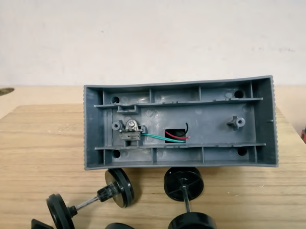
Dismantling Toby Firstly, we take out the screws holding the battery box to the underside, keeping these for retaining the new chassis later. Cut the battery leads close to the soldered joint on the box. We will replace these later, so note which is which and leave a little insulation colour on the ends. Keep the two screws and the two axles safely. You will need the one with a cam on, which is resting against the micro switch. Remove the four screws holding the battery box together. This will release the last axle. Then reassemble the box. Using a razor saw, cut off the ends through the axle recesses. This will shorten it to allow it to go inside the body later. You can cut the width down if you want by about 2-3 mm each side, taking care where the solder terminals are and set aside for later.
Take a watchmakers’ Phillips screwdriver. Remove the
four corner fixings under the skirt and the screw holding
the microswitch mounting. Keep in a safe place as you will
need the corner ones to put it back together again. Ease
the skirt away from the body and you will see a circuit
board mounted on the reverse side. Remove the three
screws and keep safe for later. The microswitch will pass
through the hole. Cut the switch wires near to the switch
and leave a little colour to tell which is which. You should
now have the skirt in your hand so put the body with the
screws. The circuit board has a large switch cover and
will fall about so don’t lose it.
 Chassis and
W irons
The chassis and skirt
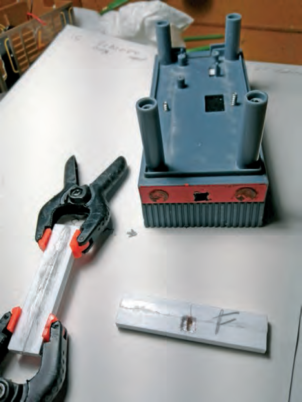
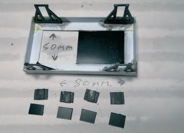
This is going to receive the most work. I used some
8mm plastic angle for the main structure of the
bogie, two 80mm and two 50mm lengths. Make a
rectangle 80 mm on the top side (see photo); clamp
and glue this together. This length allows clearance
to the corner fixings. Whilst this is setting we will
continue on the skirt.
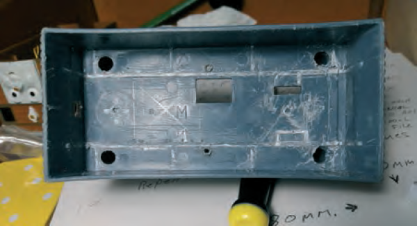
The underside of the skirt is braced to give it strength.
We need to remove this plastic to give room to fit our
bogie. Using the scalpel backwards to scratch a groove at
the base of the interior braces and the uprights, weaken
the posts that held the battery box and remove with pliers
by twisting. Also remove the stand of the cam switch. This
should give a nice clear area in the underside.
For the chassis we made earlier, cut a piece of plastic card 40 x 50mm and 1.5mm thick (the same thickness as
the angle used for frame). Glue this to the flat side of the
frame towards one end. This is to leave an opening for the
wires and motor to pass from below to the top side. Once
the motor has been fitted, this opening can be reduced to
stabilise the motor as required. A strip each side to stop
forward/backward rocking will keep the motor box
upright.
Take four W irons from your scrap box or make from the
1.5mm plastic card. Glue to the inside of the frame, to the
outer extremities, as far apart as possible. If the frame is
square then the axles will be parallel. Leave to set.
 Skirt clear cut
 Chassis fitted
 Hole cut
Axle boxes
These won't fit as there is not enough clearance between
the skirt and the W irons. The detail is out of sight so using
plastic card will give you a low-profile housing. Make new,
using the 1.5mm plastic card. Cut a strip 5 x 40mm,
enough for four 8 x 5mm pieces, two 10 x 40mm pieces
and eight 10 x 10mm pieces. Diagonally mark across all
these pieces for drilling. Step drilling will help keep this in
the centres till we get a 3mm (⅛in) hole for a top hat
bearing. Glue one small to one large piece, holes lining up.
 Axle boxes
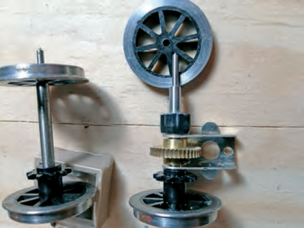
Use one of the top hat bearings from your new wheel set to align and parallel the edges. This will give you the first half of the bearing box so leave to set. These measurements are for PECO W irons. If making your own, the slide should fit to a slot 5 x 15mm deep. When set and hard, use a file to remove any glue that may have oozed out from face and edge, on the sides that slide. One of the wheel sets removed earlier has a cam on it. Cut through the axle and the shoulder that is moulded to the cam/wheel, in order to use the cam on the new wheel set. This should have the same internal diameter needed for an interference fit on new wheel set axle. Check the internal bore as this is going to fit on a wagon axle ⅛in Internal diameter and should be a snug fit. Store it safely. Sit the top hat bearing rim down. Place the prelaminated piece over the top with the smaller piece face up. Place the last larger piece of plastic card 10 x 10mm on the top, for a test fit. This should give you a slot to each side for the W iron to slide. When happy, these two pieces can be glued, avoiding the W iron. Use the top hat to assist alignment. When dry, insert the W iron. You may need to file in the grove to remove glue that has come out of the joint. Make sure the iron slides up and down. You can dry fit these to test wheel sets.
Buffer Beams
Cut four 57mm lengths of 7 x 5mm plastic flat bar, glue these by their edges in pairs and clamp. When set, mark a centre line for the vertical and draw-bar hook. The horizontal is off centre to allow the cut for the hook towards the lower edge of the beam. Aim to leave enough to conceal the rear side which has to be recessed for the spring. Leave 2mm up and then the slot for the hook. The rear needs a recess for the spring so about 5mm wide and not right through; 3mm deep should be enough. Step drilling this is easier by hand as a drilling machine is a little quick. The buffer heads are 40mm apart and 20mm each side of the draw hook. Keep these low down so you need the outer side of the body/mounting flange not to go over the lower edge of the beam. Mark to suit. Drill using 1.5mm drill for a centre.
If the file is coarse it will help the solvent bond it together later. Now clamp the buffer to the model, to give an accurate position of holes, buffers, and draw hook. To give marks for an enlarged hole to the rear of the beam, use a 1.5mm drill and mark through to the body.
Open these out with reamers or a larger drill. Make sure the holes don't show past the buffer beam edge. The holes in the beam for the buffers can now be enlarged, for the rear of the heads to go in. The hole in the model allows the spring and rear rods to clear the body. The buffers can be superglued on. As the nut cannot be reached afterwards, putting a spot of nail varnish on the nut and end thread now will help secure them. Paint glue to body and rear of beam; leave for a few minutes and repeat. Now clamp in position gently and apply glue to the top and bottom edges. The glue will go in via capillary action to parts you cannot reach. It will also re-activate the glue already in, to make a better bonding action. Solvent will attack the model’s finish so take care. The same applies to superglue otherwise you may be looking for more buffers.
Chassis to skirt
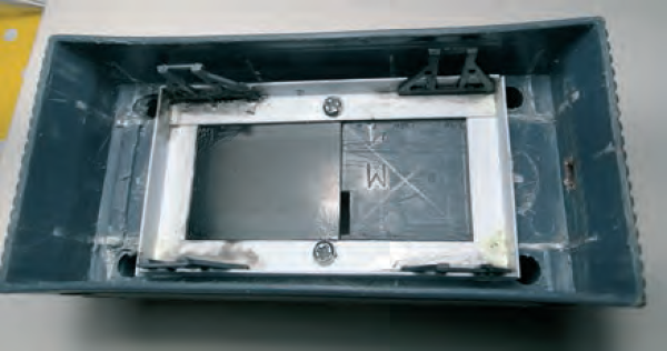
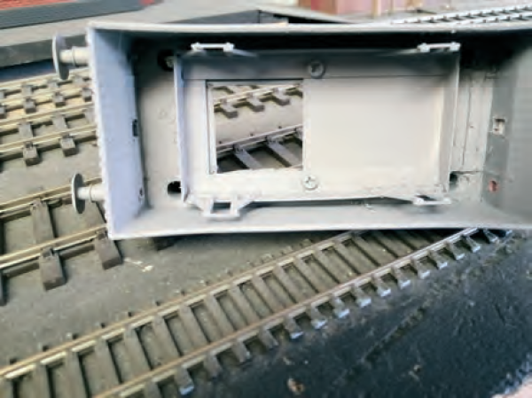
The chassis has a rectangular hole in the top side. When you place this in the skirt, you need to make sure you are not blocking the chassis hole with the circuit mount’s end. So, position centrally, front, back and sides. This should now be clear of corner fixings. Mark the angles of chassis at mid-point and drill 1.5mm holes through chassis and through the skirt floor. The holes in the chassis can now be opened up in size, to allow the bolts from the battery box retention to clear. The same bolt can now be screwed into the skirt. Holding the chassis in position, mark the open end of the chassis (large square hole) through onto underside of the skirt, using the back edge of a Stanley knife or scalpel to score this. Constant scoring will remove it, to allow motor to rise into main body chamber. At this stage you can remove for painting. It can be primed and finished in satin black. Pick out buffers and beam in red.
Wheel sets
For these I have used Slaters 7121 plain spoke wagon wheels. We need to take one wheel off the axle. Engineers’ pliers have a round grip part. Use this to go around the axle you need, to keep this score-free. Do not grip the axle tightly. It is to give you a shoulder to rest the wheel flat whilst we hit the pinpoint end of the axle with a soft-face hammer. This should release the wheel from the position on the axle. You must do this to both axles. One axle is going to have a Delrin sprocket on; this can be installed and the wheel reinstated to the axle. The second axle needs a Delrin sprocket to match the position of the first axle, pushed on to the far side.
At this stage you need to assemble the gear box. I used a Branchlines RU 40/1 metal worm, for a Mashima 14 x 30mm flat-can 5-pole motor. This gear box has a ⅛in axle bore through the gear wheel, which is why I am using Slaters’ wagon wheels. The RU mount has got ears. These are going to help support the microswitch for the cam, to reinstate the chuffing noise of the original model. Take the gear box and drill the fixings for the motor, step-drilling as they are marked. My motor has 10mm fixing centres. Fold up the gear box and solder the etched fold grooves, first making sure the folds are at right angles. Try the bearings in the box wall to see if there is a cusp from etching needing removing. A few strokes of a rat tail file should suffice. Solder into position. Now test with the axle for free movement. There is only a little thickness so take care when opening these.
Tin the ears of the gear box that are facing the axle, ready for the switch bracket. It doesn’t hurt to do both as you don't know which side will be the mount position. Fit to the motor and insert the axle with the cam towards one side of the gear box to suit the microswitch mounting. The Delrin sprocket goes on the other side. Leave the worm till later as it allows you to turn the cam for an operating position.
Bend a right angle in a piece of brass thin shim 20 x 8mm, to give a little room to position the 15 x 5mm microswitch. Sit the switch into the angle with the lever arm flush to the edge, so the bracket does not interfere with the cam. Use a drill bit with slight pressure to slide through the fixings to mark them. We need this to be drilled for 2 x ½in 12BA countersunk brass bolts. Tin the brass bracket on outside back and bottom and tin the heads of the 12BA bolts. Insert them through the bracket and bolt the switch lightly into position. Seat this on the ear that is protruding from the gear box so the cam will allow the switch to press in and out when rotated. Use a test meter to confirm that the switch makes and breaks. When this is working, remove from the ear mount and solder the bolt heads use 188C solder. When cooled, reposition to the gear box and test again. This time solder using lower melting point solder to the ear of the gear box. The heat from the latter does not de-solder the earlier joint.
Solder new wires to the switch. You will need an inline mini through-plug and socket to the ends of switch and circuit board connections. The female end of the switch is connected to the circuit board end as this is a live end. If it comes apart it won't give a short. When test trials are finished, a spot of nail varnish will stop these parting. The socket allows the bottom to run separately to the top for proving trials. The ends of the 12BA bolts can be shortened so that they do not collide with the wheels. Again, a dab of nail varnish will stop these vibrating loose. Replace the wheel and fit in the axle boxes; repeat this for the second axle. Slide these into W irons and place on a glass sheet to make sure the assembly is in a stable position. If it rocks, adjust and glue boxes to suit.
Motor and pick ups
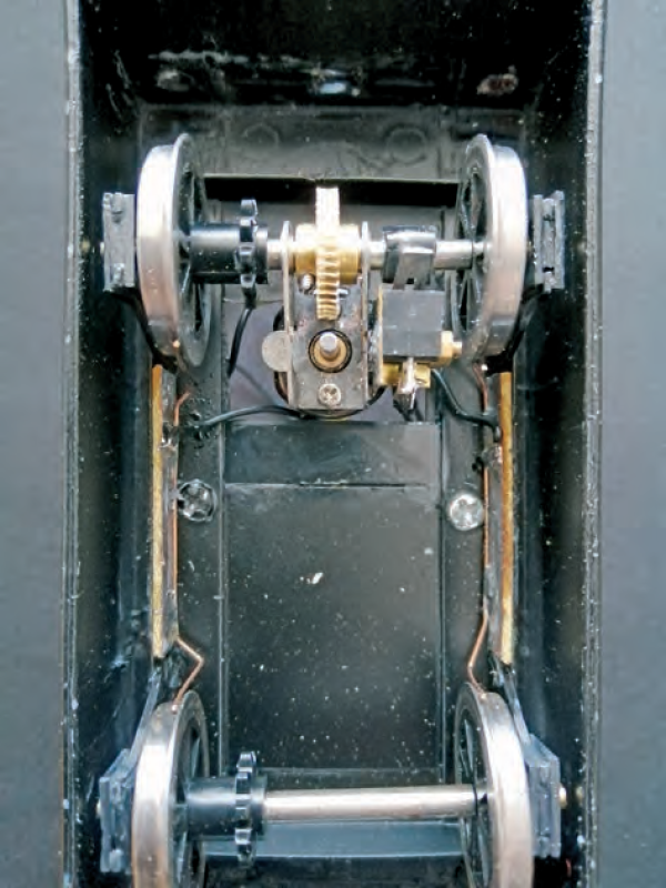
For the motor, solder two leads 150mm long and use heat
shrink to cover joints. Then take two Paxolin strips (mine
are sleeper strips 8mm wide.) These need to fit between
the W irons to your measurement and are going to be on the same side as the W irons are fixed (see photo.) Take a
piece of phosphor-bronze pick up wire. Bend this in a U
shape so that it can rub on the flats of the wheels (see
photo), where the brakes on a wagon would normally be.
As you are going to fix these on the side walls you have a
slight bow to add the other way to take up the distance
between outer frame and the wheel flats. Tin the pieces
of Paxolin, lay the pick-up on towards one edge and solder
in position. Offer to the chassis to check the fit and the
pressure to the wheels for electrical pick-up. Bend the
wire to achieve the final position. Take the motor wire
connections and thread through the opening next to the
motor to the lower side of chassis.
 Topside
Now strip and tin the ends of the motor connecting wires and solder to the opposite edge of the pick-up Paxolin. Coat the back of the Paxolin with 5-minute epoxy and clamp to the side walls. If the pick-ups are not located, make sure they will click in to position after.
Fitting the Delrin
Thread the chain under the wheel sets with the D-link at the gearbox end pushed onto the sprocket. If the D-link is on the gear wheel it will stop any movement. The spare tooth just prior to the D-link allows the other end of the chain to drop into this tooth slot. The arms of the chain drop over and can be clicked onto the D-link’s lugs. The gear wheel acts as a third hand, helping to keep it taught whilst fiddling. Pull the slack over the sprocket on the free turning wheel and offer to the end on gear sprocket. Now hold the link that has to be parted and twist it open. Push this end down on to the D end and it should click together.
Battery
Strip and tin the battery leads and reinstate to their respective positions. Wrap the case in insulating tape to prevent shorting. Several layers of double-sided tape to the top side of the skirt allows the battery box to sit on its edge alongside the motor. Check for body clearance. A flywheel can be fitted to the motor. There are front and rear lights, which are mouldings built into model. If you want to make use of these then the on-board speaker blocks the rear light moulding from a straight connection. This needs drilling at an angle and a rib will need to be reduced on the inside of the body. Connect to the motor and cover the connections in heat-shrink sleeving. Happy days.
Parts list
- 1-off plastic Toby toy O gauge size
- Double-sided foam tape
- 1-off Mashima 14 x 30 motor or similar (Branchlines)
- Heat- shrink sleeving small
- 1-off gearbox RU 40/1 (Branchlines)
- Solvent adhesive, solders and flux.
- W Irons
- In-line mini-plug and socket
- 1-off set wheels (Slaters 7121)
- Buffers.
- 8mm angle Plastruct for chassis (260mm)
- Nail varnish
- 2-off 7mm x 5mm Plastruct (buffer beams) (228mm)
- Grey primer and satin black paints
- 1.5mm plastic card infill, axle boxes, W irons
