Nick Dunhill's NER 'Whitby Tank'
Prepared by: Tommy Day
Originator: Nick Dunhill
Thread start date May 25/2017
For full Forum thread click here : -
threads/nick-dunhills-ner-w-lner-br-a6-class-whitby-tank-workshop
Nick Dunhill - May 25, 2017 at 8:39 PM
It's time to begin a new project.
The subject of this adventure is the NER W class which became the LNER/BR A6 but is colloquially known as the Whitby Tank. Two models both finished in pre-grouping NER livery as so;
 I had been given a 'NER Days' kit for one of the jobs but sold it and decided to persue a better route. Mick Davies (of Finney7 fame) took pity on me and agreed to help by drawing out some artwork for etchings to get me started. I assembled some drawings, first from the NER Association archivist Tom Burnham (great helpful chap) and later plundered the archive at the NRM. The outcome was the following etches;

 They were intended to be an aid to scratchbuilding but are actually quite comprehensive. They feature a highly detailed chassis and most parts to build the loco body. They do not include (for cost reasons) anything that is just a rectangle of brass or nickel silver like the cab roof, smokebox wrapper or boiler. The CAD did however generate the dimensions of the shapes needed to fabricate these items. A little research has revealed that most, if not all, of the Worsdell castings required to complete (chimney, dome safety valves, backhead, springs hangers etc etc) are available in the Laurie Griffin range.
So there we have it, a complete (nearly) set of parts at a very reasonable price and hours (and hours and hours) saved going down the conventional scratchbuilding route. The following pages will describe how the locos are fabricated with a guide to where to source parts. If anyone is interested in joining me on this adventure the etches are available to all (at reasonable cost!)
Nick Dunhill - Jun 6, 2017 at 5:32 AM
Here we go….

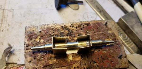
Nick Dunhill - Jun 7, 2017 at 9:48 AM ….so the inner ends of the boss laminations have been chamfered to represent the machining of the real thing. All tags filed off and all the internal end bits need the etching cusps removed prior to soldering (you can't get in there later!) All parts were then soldered together taking care to align everything. As you can see I use drills through the crankpin holes to line all up. The rest is just donkey work with files, various grades of wet or dry and finishing with a burnishing tool. Nice CAD work Mick….
Next some detail…..
paul copsey - Jun 7, 2017 at 11:16 AM
Nick , in one of the photo's , is that an old split file handle rehashed into a holder . What a great idea . Cheers Paul
Nick Dunhill - Jun 7, 2017 at 12:03 PM Sorry I'm not that imaginative Paul! It's a jeweller's ring clamp [URL]http://www.axminster.co.uk/jeweller-s-ring-clamp
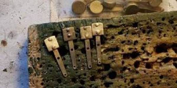
Nick Dunhill - Jun 11, 2017 at 8:12 AM ..added the adornments to the rods. The oil pot fillers and drains are made from Scalehardware components and the joint pins are scratchbuilt from rod and thick walled tube.
Nick Dunhill - Jun 13, 2017 at 7:24 PM
….so on to the chassis plates. The W was rebuilt from a 4-6-0 T to a 4-6-2T quite early on. The frame extensions were simply riveted on to the ends of the existing plates, and Mick designed a clever frame spacer to lock the two sections together. All the frame plates, original and extensions, are a lamination of two etches. The outer thin etches on the main, original, sections have to be orientated correctly. The thicker inner etches have a half-etched extension to the top portion. This needs to be innermost, i.e. the rear of the sandwich is the flat side and the outer side is the thin overlay. Care must be taken to align the two laminations exactly, and the soldering up and filing/emerying is a rather tedious process (in my view!)
The rear extensions are easy and quick to solder up but the outer overlay has a slot missing. This is shown in the pictures below but is easy to correct. After soldering the two laminations together, put extra solder in the outermost slot to hold the two pieces firmly. Drill either ends of the slot with a 0.5mm drill and cut out the slot with a piercing saw. I then used a 0.5mm drill as a slot drill (look away engineers) to define the slot properly. It works well if you are careful.
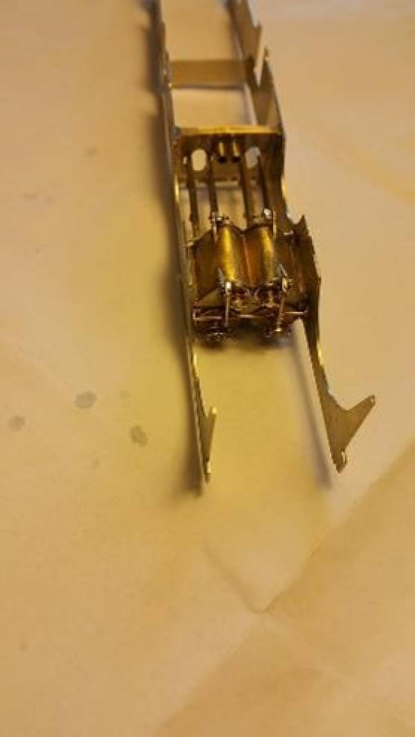
 This shows the main sections of the chassis soldered up, below, and cleaned up, above.
 The end slot is absent on the outer overlay,
 but present on the thicker inner lamination.
 Simply drill through from the inside with a 0.5mm drill and cut out the slot with a piercing saw.
 Done, and only a 2 min job.
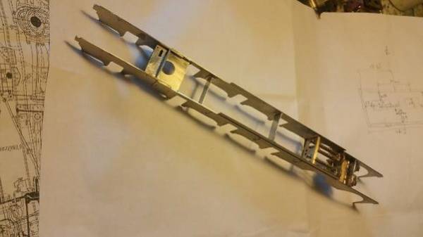
 All the completed chassis sections. Note the inner faces of the thicker, inner lamination are flat at the rear.
Next some stretchers…….
Nick Dunhill - Jun 15, 2017 at 2:31 PM
….So here are the frame stretchers. The large structure is what holds the extensions to the original frame section.


 next cylinder blocks…..in a couple of weeks…..
Podbery17981 - Jun 18, 2017 at 9:15 AM Dear Nick, INCREDIBLE work as always!
I have two questions if I may; what Scale Hardware components do you use to create the oil pots and corks? And do you increase the width/depth of the coupling rod bosses on laminated rods or do you leave them as they come so to speak? I guess an answer to the last question would be, 'it depends'. Many thanks, and once more fantastic work! Neil.
Nick Dunhill - Jul 2, 2017 at 6:15 PM Sorry about the delay in replying Neil, I have been away for a fortnight. The top fillers are a 0.8 mm rod drilled into the boss with a 0.8 mm miniature nut pushed over it (threads drilled out.) The bottom drain plugs are 0.6 mm fake bolt heads. The bosses do indeed have an overlay to fatten them. I usually do 'whatever is prototypical' on rods. Nick
Nick Dunhill - Jul 24, 2017 at 6:26 PM
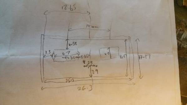
….it's been a while, but I have been making a cylinder block, slidebars and a motion bracket. The motion bracket had to be scratchbuilt and below are the dimensions. It was made from the waste round the etched panel, and the fixing plates and 'T' sections from the waste round a Finney kit.

The next pictures show the ensemble offered up to the frames.

 The cylinder front next and the cylinder drain cocks……
Nick Dunhill - Aug 21, 2017 at 8:58 PM
….I have spent a little time making lots of detail parts for the cylinder block. The cylinder heads have been fitted as have the valve stem guides. All the castings were from the Laurie Griffin Stephenson link kit for NER locos, which is pretty much spot on for this loco. The valve guides for the rear of the cylinder need to be separated as they come as one casting. Later you will see that the valve rods 'step out' along their length and consequently the guides are not concentric. If fitting inside motion the holes in the cylinder front and rear for the valve rods need re-drilling 1 mm above the ones pre etched. The valve rod guides on the motion bracket are positioned using a drill in the cylinder rear guides to act as a pointer, as the cylinder rear, slide bars and motion bracket are held temporarily on one frame plate to get the alignment correct. Next all the tail pipes were fabricated and added to the cylinder fronts (took ages!!) A brass rectangle 15.2 x 26.3 mm was cut out to act as a bridge piece between cylinder front and rear and a curvy W shaped cylinder bottom added from brass sheet. Next all the cylinder drain cocks and many linkages were made and finally fitted. Details of the linkages can be found on the pipe and rod drawing on my Flickr account.
http://www.flickr.com/photos/144381574@N05/albums
[img]https://farm5.staticflickr.com/4357/36672718596_3a3e50ac8b_b.jpg[/img]


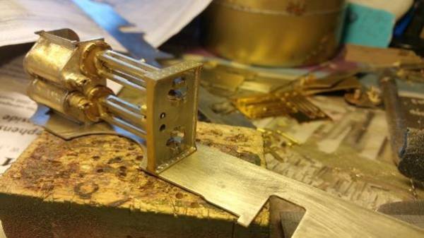


Should be able to assemble the frames now the cylinders are finished. Will hopefully have some show-and-tell for Telford.
Nick Dunhill - Aug 23, 2017 at 8:48 PM
……it's been a good day. I have spent weeks cutting out and fettling castings and etchings, making linkages and pull rods and brackets and rods for the cylinder blocks. Today I stuck them all together and have a basic chassis. All the frame etchings fit perfectly, just remember to double check everything for perfect alignment before you begin to solder. I raise a glass to the designer…..


———————————————————————————————————
Nick Dunhill - Aug 29, 2017 at 7:44 AM
….every day a school day! For the first time I have to make buffer beams that are a wooden 'sandwich.' I would welcome suggestions for the best type of glue to bond the wood to the N/S beams please.
 Thanks….
Ian - Aug 29, 2017 at 8:01 AM Araldite works for me! Ian
Nick Dunhill - Aug 30, 2017 at 8:30 PM
…the wooden 'filling' was glued (epoxy, ta) to the outer buffer beam after the buffers had been fitted (modified LGM castings.) [The buffer stocks have had a small collar soldered to the ends to improve appearance and the locating tube removed from the rear. The buffer heads are held in place by soldering a small washer to the stem and trimming as appropriate. The buffer movement is contained in the wooden portion of the buffer beam.]
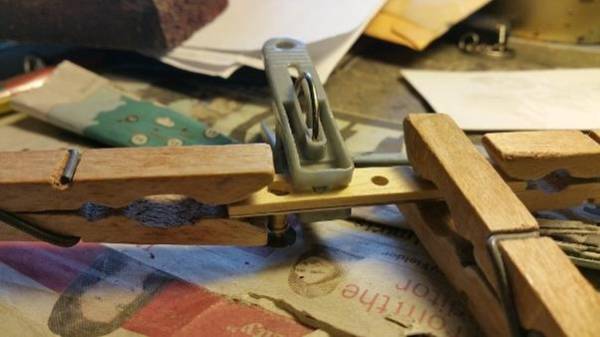

Final assembly of the rear beams was done on the chassis. The inner beam was soldered to the end of the chassis, checking for squareness in all planes. The outer assembly was glued into place, again checking alignment very carefully (I used a 1.7mm drill through the coupling hole to help.) The wooden portion had a notch cut in the top to allow access to the locating tab with a soldering iron tip. Soldering adds much more strength to the sandwich. Angle iron strengtheners, as prototype were, added. The designer had kindly added etchings for the triangular gussetts (hero,) also added.
The slots in the front buffer beam etchings are in the wrong place. The frames are wider at the front of the loco than the rear and the slots are to suit the rear only. It's an easy fix though. I had to make some locating tabs like this, from material the thickness of the chassis plate;
 and assembled the front buffer beams by soldering the locating tabs to the rear beam and glueing and soldering the front assembly in place. I added a strip to disguise the locating tab as the angle iron strengtheners thus;
 The slots are in the wrong place by a distance equal to the thickness of the chassis plate (x2) so the front beam can be easily soldered in place now, again carefully checking alignment.
The coupling hook on the rear of the loco is very long, as when the loco was rebuilt the original drag box was used. This necessitated a very long hook to reach it. It was fun to build prototypically.


 It'll be at Telford on the Modelling Competition/Sunday Display stand all weekend for inspection. See you there?…….
Nick Dunhill - Sep 10, 2017 at 4:23 PM
……I've managed to fit up the footplate to my W or A6 chassis. It was easy as the footplate is a sub millimetre fit. Good design again. I suggest to anyone making one of these from my (and Mick's) parts to put the outer part of the buffers on the chassis AFTER fitting up the footplate. That way you won't have to realign any buffer beams later. They do fit perfectly but best to use the footplate as a jig. It is also very important to get the chassis perfectly straight and square. Also if you're adding all the cylinder head details you'll need to cut away sections of the footplate to accommodate them. Sorry about the poor pictures……

Nick Dunhill - Sep 11, 2017 at 8:01 PM
…a bit more progress today. I have made some brackets to fasten the chassis to the footplate (body) thus;
 And will take some steps to disguise the screw head later (don't like screw heads on view!)
I then fitted up the valances to make a nice crisp chassis/footplate on which to build upwards.
 Next the chassis sections above the footplate….
Nick Dunhill - Sep 21, 2017 at 8:19 PM
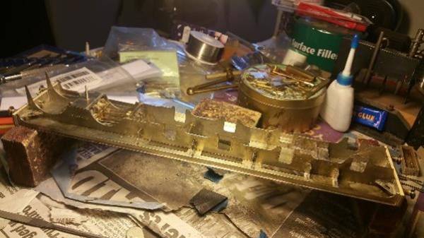
…so over the last few days I have sorted out the brake hangers which on a lot of NER locos seem to double up as the footplate support brackets. The ones on the etches are good but I have detailed them up a bit and and attached them to the chassis in the half etched locating holes. There are an additional two brackets on each side that are not on the etchings. Just draw round the brake hangers provided and cut them out. They're the same shape. Here's all fitted up.


More footplate offerings next…..
Nick Dunhill - Sep 27, 2017 at 9:12 AM
….I have built the steps.
 Although the front steps have backing plates on the etch, they aren't handed (oops!) It's an easy fix though filling the slots (I used old boiler band strip) and putting the treads on the rear.
 These were then fitted up to the footplate and I have begun adding all the angle iron and strip that's present under the footplate to hold everything in place.


More to come as the work progresses.
Nick Dunhill - Sep 29, 2017 at 5:50 PM
…..I finally finished adding all the runs of angle and strip for under the chassis. They are present on the prototype to support the footplate on the chassis and to strengthen the buffer beams. Oddly the rear coupling hook is attached to a substantial drag beam, but no such structure exists for the front coupling, the buffer beam transmitting most of the weight of the train. Clearly the NER turned their Whitby tanks a lot!


Next I moved on to the section of the chassis above the footplate. The two etches to be laminated don't match, but again an easy fix. The outer portions are correct, the half moons for the splashers are in the wrong place on the inner etch.
 Here's what I did. First make a cut through the inner lamination, the one with the rebate . I did it near to the front of the front 'moon.'
 Then solder the rear portion of the inner etch to the outer etch aligning the half moons.
 Then I cut off the bit hanging over the end and soldered it to the front.
 It's all self explanatory looking at the pics. Then solder the front of the inner etch to the outer etch and make good….phew. Easier than it looks honest.
 Will attach chassis sections next…..
Nick Dunhill - Sep 30, 2017 at 7:47 PM
….so I have attached the cut and shut upper chassis sections.

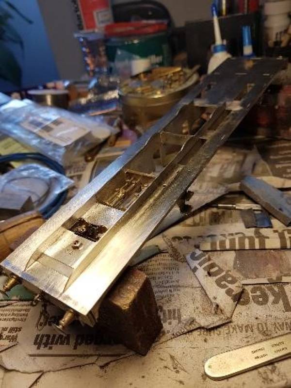

Some hidden pipework next as a bit of light relief from all the sheet fabrication and making good!…….
Nick Dunhill - Oct 5, 2017 at 6:06 PM
…so the Ws now have water balance pipes connecting the front and rear tanks (made from annealed 2.5 mm square brass) and feedwater pipes from the rear tank to the injectors.
 Axleboxes next…..
Nick Dunhill - Oct 13, 2017 at 10:15 AM
…so on to the horn guides and axle boxes. I was going to use Slater's cast horn guides but they turned out not to be compatible with the frames. Finney7 leaped to the rescue with their Hall axleboxes. With a little modification they became a very close representation of the NER ones. They do take ages to build, 72 triangular webs to add to 12 hornguides, but they look the part when done.


The machined axle boxes for the front drivers were replaced with Slater's items. They drop straight in and are thinner and yield the space required to accommodate the crank webbing and eccentrics of the inside motion. The horn cheeks are cut down to suit.

The axle box assemblies were then soldered in place using jury axles and the coupling rods as a jig. Careful alignment was necessary and extra temporary cross members were added to prevent the springs spreading the frames.

I'm going to have some fun building ash pans next…..
Nick Dunhill - Oct 17, 2017 at 8:33 PM
…ashpan action! The ashpans were fabricated from waste material round the frame of one of the panels of etchings. Firstly a side piece was cut out following the dimensions on the GA to check the fit of the gearbox
 Then the front, rear and bottom pieces required cut out.
 And the bits soldered together using squares.
 Then dampers and hinge detail added.
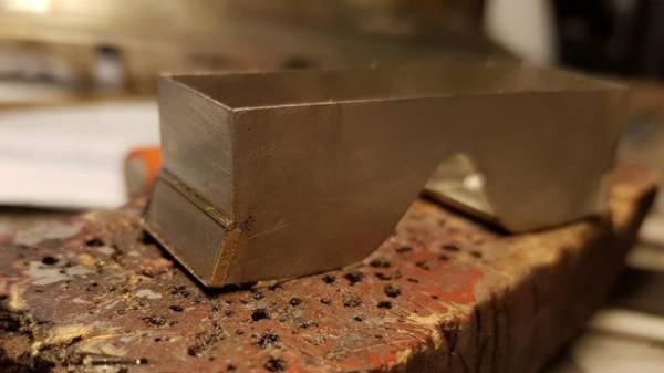

Next I will fit them to the chassis and add the control rodding…….
Bob Alderman - Oct 17, 2017 at 9:38 PM Nick I take it on the prototype the ashpan was each side of that axle? You have just left out the part that goes over the axle? Bob
Nick Dunhill - Oct 17, 2017 at 9:45 PM Bob The shape of the ashpan side is prototypical. It's v shaped so that the axle doesn't go through it. Odd but interesting! Nick
Bob Alderman - Oct 19, 2017 at 12:03 PM Not uncommon. Similar on other locos but perhaps not so pronounced. Bob
Nick Dunhill - Oct 19, 2017 at 12:22 PM Ah. Must be more vigilant in future. Of course though, the axle is never going to go inside the ashpan.
shedman - Oct 20, 2017 at 10:49 PM Hi Nick I might have missed this somewhere, but is this model based on one in pre-grouping condition? Terry
Nick Dunhill - Oct 21, 2017 at 2:03 PM Yes Terry the models will be as running in about 1914 with early buffers, Ramsbottom safety valves and no bogie brakes. NER lined green.
Nick Dunhill - Oct 21, 2017 at 2:03 PM
…the ashpan has been fixed into the chassis and some control rodding for the dampers added. I have also added the control rodding for the cylinder drain cocks. The ashpan and all the rods have been made from waste strips from etchings.
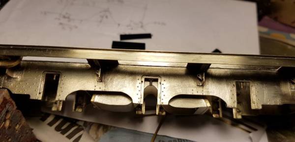

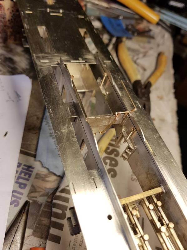

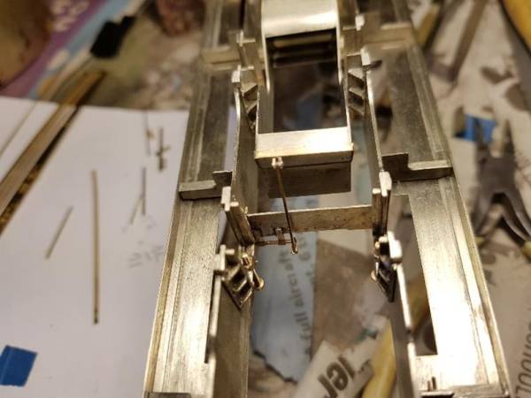

Springs and hangers next (maybe)……..
Nick Dunhill - Oct 29, 2017 at 5:53 PM
…bit of pattern making this week. J hangers and equalising beam for loco suspension, An injector, an anti-vacuum valve and an atomiser for the cab.

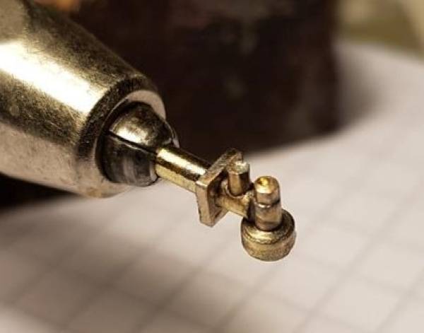
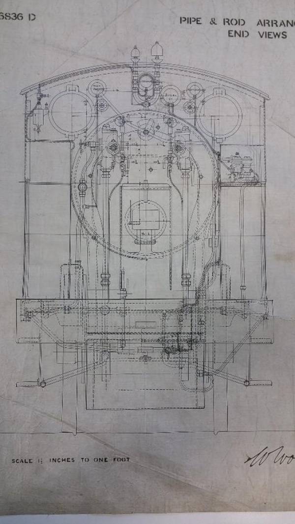
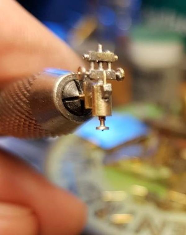
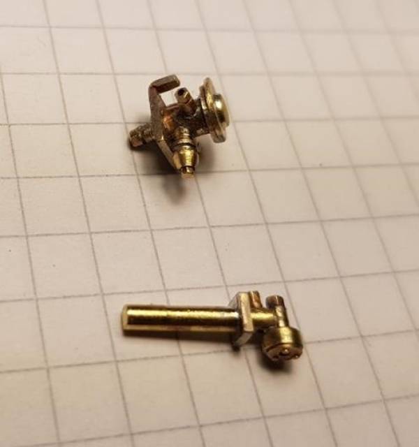

Someone is machining me a sand box and I'll make a reversing lever when I've made the tank inner inside the cab…..
shedman - Oct 30, 2017 at 3:00 PM Hi Nick How do you ensure all the detail is not lost with painting? Terry
Nick Dunhill - Oct 30, 2017 at 5:55 PM
Hello Terry. Warren Haywood paints my models and he (as a professional painter) uses cellulose based paints which go on with micron thickness and the sharpness of everything is preserved. Nick.
Nick Dunhill - Oct 31, 2017 at 7:51 AM
I'm after a Mason Reducing Valve casting. If you look at the drawing and the LHS injector, there is a pipe coming out of the left side. I believe that's the steam heating pipe, and if you follow it, it goes through a Mason Reducing Valve (pot bellied thing) and off through the cab floor via a larger diameter pipe. Apparently they're standard GWR fittings so someone must do a casting for it. Any ideas anyone?


Ta…..
END OF PART 1 OF 'WHITBY TANKS'
CONTINUATION PART 2 'WHITBY TANKS' : -
Nick Dunhill - Nov 1, 2017 at 7:34 PM
….I have curved the splasher tops and located them on the footplate using the inner tank panel. Then I soldered the inner tank panel in place and added the cab front.


 I also finished the last pattern, for the reverser.
 More panelwork next…..
Graham Bustin 9984 - Nov 1, 2017 at 9:06 PM Nick, Can we have further details about your pattern making please? Graham
Nick Dunhill - Nov 2, 2017 at 1:53 PM Hi Graham. There's no secret. You just take the dimensions of the part from the GA and make it from brass or nickel silver. Be sure to use higher melting point solder (I use electrical solder 230°C I think) as there's a part of the lost wax casting process that requires heat and can melt lower temperature solder. You can see lots of pictures of patterns I have made above or on my Flickr page here; https://www.flickr.com/photos/144381574@N05/ Where you can also see lots of unposted pictures from my builds as well as drawings of the Ws
RobinMcHugh - Nov 3, 2017 at 12:38 PM Hello Nick, Do you not allow for shrinkage when patternmaking, particularly when using a lost wax process? When I was doing this on a regular basis many moons ago, I was advised to allow around 2-2.5%. A jewellery making company in Fife made moulds, waxes and castings for me but unfortunately they've retired now so I can't check whether this is still what would be advised, Robin
NigelSmith - Nov 3, 2017 at 4:24 PM Hi Robin, When we do ours they don't normally need shrinkage built in for small castings, but for the larger ones they do, (we use casters in the Jewellery Quarter Birmingham). Cheers Nigel
Nick Dunhill - Nov 4, 2017 at 5:51 PM HI all. Its around 3% shrinkage which is taken into consideration. I'm going to use either A Wardles in Brum or Slater's in Darley Dale. The later is close to me. Nick
Nick Dunhill - Nov 4, 2017 at 6:03 PM
…so loads of bodywork. The splasher tops have been curved and fitted using the inner tank panel as a guide. (As an aside I ran a 0.5 mm drill along all the slots in the footplate as they give a better fit for the tabs on the bodywork.) Then I fitted the cab front into the footplate and the tank inners and soldered up. I added bits of scrap to the splashers to complete the illusion of them having a front and rear.
 Note the snotty soldering! The cab tank inners were added to the footplate using the cab/bunker/tank outer panel as a guide. The handrail holes have been drilled, but the main panels will be fitted next after I have made cab doors. If you're making one of these from my etchings you will need to shave 0.3 mm off the tank tops to allow a nice fit for the cab sides.
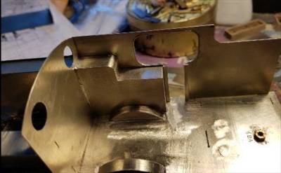


Still on with the cab doors…….
Nick Dunhill - Nov 10, 2017 at 8:10 PM
….so on with some more fabrication. As you can see I have added the beading strip that goes round the perimeter of the cab opening. It's on the etchings hidden down one side. The rivet strip round the beading is from an etch produced by Scale Link (sheet SLF016.) The cab doors have to be scratchbuilt. I took the tortuous route of making working hinges, they're also made by cutting short lengths of the above rivet strips and bending round a 0.6 mm drill shank. The latch also works!
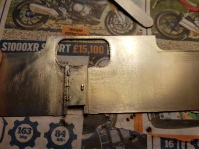

The cab/tank/bunker sides were then added. All the parts are a very good fit so care must be taken to ensure the tabs fit fully in the slots. As I said earlier I had to shave 0.3 mm off the top (side) of the tank inner etch so that it locates in the half etched slot in the cab/tank/bunker side AND meets the cab front. One of my models needed a fraction shaving off the sides of the cab front, rear and bunker rear to get a perfect fit, the other did not. Obviously variations in the etching time….
 Detailing the cab sides a bit then adding the cab rear next…..
Nick Dunhill - Nov 10, 2017 at 8:31 PM Can anyone help with the detail on the rear of the cab and bunker? The cab rear has some device for showing water levels (?) on the driver's side? The bunker rear appears to have a step on it. Which side? Is it on the driver's side above the buffer step? Does anyone have any detail about how the buffer step is attached? Ta Nick
Nick Dunhill - Nov 14, 2017 at 5:40 PM
…..cab door handrails. I bought some Laurie Griffin tapered handrails and they have cleaned up nicely. Spinning them in a mini drill and polishing them with wet-or-dry (hold both sides) straightens them up.
 I measured the position of the base holes for the handrails off the GA and pre-drilled them before soldering on the tank/cab/bunker sides. To my horror the cab cut-out beading was slightly too short (also to be completely accurate it's offset so that is thicker on the inside than the outside.) Here's how I got round it.
 Ends too short, so splice a bit in. There's some scrap material on the etch that's the correct thickness. Solder with high temp solder (electrical at 240deg.)

Add the handrails with lower temp solder, 140 deg.
 Cut out the unwanted bit with a piercing saw carefully and make good.
 Or with the benefit of hindsight you could drill the base holes half a mm to the left/right and avoid all the above malarkey….your call……
BIGGS22673 - Nov 14, 2017 at 6:38 PM Hello Nick Sorry about this, I expect you’ve been asked it many times before. But what do you use to polish the brass, it always looks superbly clean, and I assume you do it after each soldering session. Dave
Nick Dunhill - Nov 14, 2017 at 7:39 PM Hi Dave I don't really know. I have terrible problems with corrosion with some kits but this one's been ok. Perhaps because it's nickel-silver rather than brass? I wash after pretty much every session, but I use a liquid flux and the stuff gets drawn between plates by capillary action, only to re-appear later to do it's stuff. Perhaps it's because I've not let the flux become too concentrated. I think if you leave the top off the bottle or dip your iron tip in it (baaad habbit) it concentrates it and it becomes more corrosive? I clean up the parts with worn wet-or-dry (other waterproof abrasives available) and a fibreglass pencil. A bit of gossip for you though. Some modellers, mentioning no names, polish their models specially for photo shots to make them look better. Spending hours with a burnishing tool and squaring up the Blu-tac holding stuff in place, expensive lighting and multi million pound camera equipment. I have to admit to being a bit remiss in that department though. Hope this helps. (Clean after every session, remove tarnish before it gets too bad.) Nick
Bob Alderman - Nov 14, 2017 at 8:38 PM The water gauge. Have look at your drawing and see if there is a vertical pipe against the cab bunker plate. Probably in the rear left corner, with a cock at the bottom. It is perforated along the length. When the cock is turned on water gushes out of the holes. The highest point indicates the water level. It seemed to be favourite solution in the NE to determine tank contents with one of these pipes. Its use continued to the Peppercorn A1's. Bob
Nick Dunhill - Nov 17, 2017 at 5:52 PM …..have made a start on the cab rear prior to fitting up. Have made the hatch and runners for the shovel plate. The water level gauge is interesting. In later years it had a perforated tube (turn handle water pees out showing level) as most LNER engines, but in the early NER days it had a glass tube within a steel pipe to show water level. I have filed the holes out of a bit of thin walled tube and intend to drop a length of NS rod inside it to represent the glass tube after painting.
Thanks to Tom Sherlock Burnham for spotting that. The other thing Tom spotted that I'm not so enamoured with are the 10 bars over each window. Bahhhh! The eagle eyed amongst you will spot that the loco now has buffer steps.
 Next window bars…….
Nick Dunhill - Nov 21, 2017 at 6:39 PM
…I have fitted up the bunker rear which is the last of the big parts in my etchings. The part fitted well but here's a summary of the minor faults I have found. You'll see above we had an issue with a slot only half etched in one of the chassis members. Easy to resolve. The second problem is one of the step backing plates that is not handed, ie both parts are for the same side, again easily resolved. One of the upper chassis laminates is wrong but easily resolved using the cut and shut method above.
The main body parts fit very well. I had to trim about 0.3 mm off the horizontal outer edge of the tank inner etches. I scribed a line and whizzed the extra material off with a sanding disc in my mini drill. The cab front, rear and bunker rear need 0.15 mm whizzing off each edge to fit comfortably between the cab/tank/bunker sides. Scribe/mini disc again, minutes work. One of my cab rears needed the height reducing by 0.3 mm (I filed material off between the tabs) the other did not, so maybe this is an etching discrepancy, or me putting the two sections together carelessly. Finally the slots for the bunker rear are about 0.25 mm too far to the rear. I reduced the thickness of the tabs by a similar amount (30 secs) and all fitted well. Nothing on the scale of some (A Kits, eh?) kits and not bad for some etches that weren't beta tested.
 The bunker rear is tricky to form. Mick has etched the panel purposely too tall, to aid bending, with trimming required afterwards. I utilised the extra material to grip the panel and form the curve. I marked out the start of the curve with a marker pen and stuck the top edge of the panel to the centre of a 12 mm diameter bar with double sided sticky tape. Grip the edge of the panel and bar (upside down with tabs uppermost) in the safe jaws of your vice. Bend the panel round the bar, using a heavy straight edge, up to the marker pen line. Second time I was lucky and got it more or less right first bend. First attempt needed to be bent a bit more after offering up. Be careful not to solder the footplate to the bufferbeam via the locating slots as I did!
We plough on…….
——————————————————————————————————–
Nick Dunhill - Nov 24, 2017 at 9:16 PM
…..The bunker top (coal raves?) This was a very fiddly and tedious job. The bunker was lined with some strip on which the bunker top sits. I stuck strip to the underside of my ruler with double sided tape and soldered it to the inside of the bunker.

 It doesn't need to be too neat as it will be hidden. Next I made the bunker top in strips. I soldered half round strip to the edge of thin sheet and then used a (1 mm) drill shank to space the second strip. The piece was cut off the sheet and repeated.
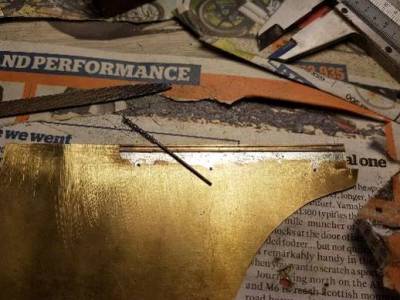
 The sides of the bunker top were cut to size, chamfered on the ends, and soldered onto the previously added strip. The outer edge of the half round strips in line with the bunker sides, easy to achieve with a flat strip of brass.
 You can see it was just tacked at this stage. The rear strip was cut to length and chamfered to fit. I constantly checked everything was straight and square. Then the final soldering up was done and a representation of the brackets added.

 Not sure what to do next, back to cab detail probably…….
————————————————————————————————————–
Nick Dunhill - Nov 27, 2017 at 4:53 PM
….lovely shiny things. Took an age to sort out, dodgy 1980s castings mutter mumble mumble…..


 ——————————————————————————————————-
Nick Dunhill - Nov 28, 2017 at 9:28 AM
Anybody know where I can get a decent Westinghouse Valve?
 Thanks
———————————————————————————————————–
StephDale - Nov 28, 2017 at 10:02 AM
Precision Scale? Via EDM perhaps.
Steph
———————————————————————————————————–
Nick Dunhill - Nov 28, 2017 at 10:28 AM
Who?
====
ThomasHeller - Nov 28, 2017 at 11:20 AM
There must be some of them in one of my drawers … will need a little time for searching! :)
——————————————————————————————————–
StephDale - Nov 28, 2017 at 11:54 AM
Precision Scale. Catalogue here:
https://www.precisionscaleco.com/wp-content/uploads/2017/03/O-Steam-WOP.pdf
You want page 34 for brake controls.
Steph
———————————————————————————————————-
Nick Dunhill - Nov 28, 2017 at 8:55 PM
…….boiler water gauges for the W. I cleaned up the castings, added a bit of handle detail and cut out the cast 'glass' safety box.
 The two ends were mounted in the backhead and held in place by bluetac.
 Perspex safety glasses were cut and drilled down the middle to represent the sight glass. Stripes were printed out and cut into strips.
 They were stuck to the rear of the Perspex glasses and glued in place between the cast ends.
 A bit fiddly but much improved appearance. More backhead action to follow……
————————————————————————————————————–
Buckley10339 - Nov 29, 2017 at 7:49 AM
Are they Laurie Griffin castings Nick ?
Pat.
—————————————————————————————————————
Nick Dunhill - Nov 29, 2017 at 9:27 AM
They are indeed Pat.
————————————————————————————————————–
Nick Dunhill - Dec 8, 2017 at 6:58 PM
….more backhead/control detail. I have added most of the backhead detail, gauges and Westinghouse brake pipes (there's a lot of the latter.) All of the connectors, T-pieces etc have been hand made from brass tube. The pipe fittings were cut off the gauges and they were spun in a mini drill and cleaned up to improve their appearance. New pipe fittings were added later. All the pipe runs and fittings are removable for painting. (Lucky boy WH!) The blinder was scratchbuilt from scrap etch.


 More pics here: https://www.flickr.com/photos/144381574@N05/with/38030939425/
Next I finish the backhead horror…..
——————————————————————————————————————-
Bob Alderman - Dec 8, 2017 at 8:18 PM
Nick
Are there damper controls to add at the foot of the backhead, or thereabouts?
Bob
—————————————————————————————————–
Nick Dunhill - Dec 8, 2017 at 10:06 PM
There'll be damper controls on the floor and more small reversing quadrant style levers to work the cylinder drain cocks and front sanders. Wonder where the control for the blower is?
——————————————————————————————————-
Tom Burnham - Dec 9, 2017 at 2:15 PM
Nick,
There is a rod that passes along the upper part of the boiler on the fireman's side and connects to the blower valve on the side of the smokebox. The hand wheel for this can be seen just below the train heating gauge on the end pipe & rod drawing. Similarly, a rod passes along the driver's side to the steam cock for the Westinghouse pump.
Tom.


 —————————————————————————————————–
Nick Dunhill - Dec 20, 2017 at 8:46 PM
…..a bit of woodwork. A lot of Worsdell tanks have a neat Ikea cupboard (see 7mm Mick's post in Geordie Bruiser p4.) The Ws are no exception so here's how I made mine. The Carcass is made undersize from nickel silver waste etch. It is covered in 0.8 mm veneer with the doors carefully scribed in the front. The edges are radiused and the hinges and hasps added.

 Water vent pipes next….
———————————————————————————————————-
Nick Dunhill - Dec 21, 2017 at 4:18 PM
…Santa's been!! Fresh from Slater's, castings for the suspension, cab and other parts for the W. Will be posted out to all that ordered them soon.
 ————————————————————————————————————–
Nick Dunhill - Dec 27, 2017 at 12:39 PM
…this is one of those 'don't have a lathe' improvisation posts. Apologies if you have one, this will be an easy 'make' for you. I bought some tank vents from Laurie Griffin for an LMS tender and they were way too hefty, so I set about fabricating some. As luck would have it I had some 1.2 mm rod for the stem and two sizes of telescoping tube to go over the rod to give a big increase in diameter. The whole thing was trued up in a mini drill and filed to the correct shape. It can also be cut to size in a mini drill using a piercing saw.
 holes were then drilled through the stem just below the 'mushroom' cap and flattened bits of rod soldered in them. These were shaped to represent the brackets that hold the cap onto the stem pipe.
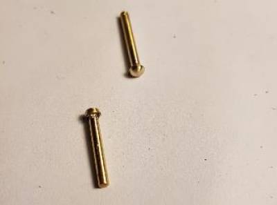
 Next, fitting up reversing lever and planking cab floor. Does anyone know if the W had lubricator boxes for the rear axleboxes on the tank sides inside the cab?……..
————————————————————————————————–
Tom Burnham - Dec 27, 2017 at 7:09 PM
Nick
There is a dual outlet lubricator box that supplies oil to both the rear and centre driver axle boxes shown on the Pipe & Rod drawing. It is located high up on the tank side as shown centrally on this extract from the drawing.
 It is of the same type as this one fitted to the preserved J27.
 I can't find anything for the trailing radial axle box as the Pipe & Rod drawing is only for the 4-6-0 version and nothing is shown on the Alteration to Main Frames or Back Tank and Bunker Drawings.
Tom.
————————————————————————————————————–
Nick Dunhill - Dec 28, 2017 at 8:27 AM
Thanks Tom. I spotted that after I posted, but couldn't find anything for radial truck either. The lube box for front driver is shown attached to the inside of the tanks at the front. Didn't they move to the front of the tank? Seems a bit inadequate only having one pipe to each axlebox. Usually the horn cheeks have a supply each and the bearing journal one too.
—————————————————————————————-
Tom Burnham - Dec 28, 2017 at 3:05 PM
Yes Nick, all the photos of the rebuilt locos that I have access to show a dual feed oil box attached to the tank front like this. The original had only one feed so where the second pipe on the replacement went to is a matter of conjecture. Did Mick obtain the Pipe and Rod drawings for his A7 build as the arrangement will be similar to the Class W (A6)? Photographs of the Class Y (A7) in original NER condition show a dual feed box in the same position on the front of the tanks.
Tom.
 ————————————————————————————————
Tom Burnham - Dec 29, 2017 at 6:34 PM
I've found two photos of the cab of an A7 taken at the Darlington scrap yard showing four outlet oil boxes. I'ts likely that this is the arrangement used on the Class W after rebuilding as a 4-6-2 with the front two pipes going to the center and rear drivers as before and the rear pair supplying the trailing radial axle box.
Tom.

 ————————————————————————————————–
Nick Dunhill - Dec 29, 2017 at 8:53 PM
Bingo. Good detective work. That would make a lot of sense. Oil for the axle journal and one for the radial slides. Still a bit perplexed about the single feed of oil to each axlebox. More modern engines have a gravity feed to each horncheek and a pressure (mechanical) lube feed to the axle journal. Obviously it works though so I shouldn' worry. Wonder if there's a hidden lube box behind the tanks (where the original single feed one was) supplying the middle axle?
Anyone any idea how wide the planking on the floor of this loco would have been? 6
————————————————————————————————–
Nick Dunhill - Dec 29, 2017 at 8:53 PM
Bingo. Good detective work. That would make a lot of sense. Oil for the axle journal and one for the radial slides. Still a bit perplexed about the single feed of oil to each axlebox. More modern engines have a gravity feed to each horncheek and a pressure (mechanical) lube feed to the axle journal. Obviously it works though so I shouldn' worry. Wonder if there's a hidden lube box behind the tanks (where the original single feed one was) supplying the middle axle?
Anyone any idea how wide the planking on the floor of this loco would have been? 6,8?
——————————————————————————————————–
MartinShaw - Dec 31, 2017 at 10:10 AM
Nick
It's entirely possible that the axle journals are fed from a reservoir created in the top of the axlebox, and the oil boxes visible are purely for the horns. Sort of adds up then.
Regards
Martin
————————————————————————————————
Nick Dunhill - Dec 31, 2017 at 6:27 PM
8 ins would make sense as the cab is 11 x 8 inch planks wide exactly.
—————————————————————————————————
Nick Dunhill - Dec 31, 2017 at 8:29 PM
….so the front tank vents have been made. they are built from 1.4 mm tube telescoped over 1.2 mm tube. The base dimensions are shown and the side pipe is from 1.2 mm rod. brackets have been added from riveted strip. The vertical section of the angle iron that secures the cab roof has been added to the cab sides and front/rear.


 All the cab fittings were added to the model and a false floor added prior to a final floor skin.


 Next more flooring. Happy New Year…….
————————————————————————————————————
Nick Dunhill - Jan 3, 2018 at 5:40 PM
…so the cab is done. Well not quite it needs 2 4-way lubricators and a roof. Will do later.


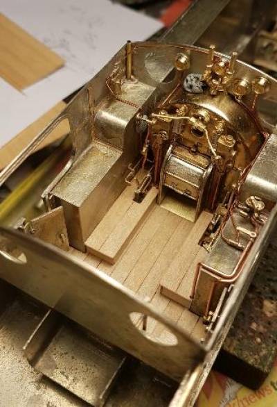
 Roof next…
————————————————————————————————————-
Nick Dunhill - Jan 9, 2018 at 9:59 PM
…..cab roof. I started with a card template to size the upper roof and worked out I needed a rectangle 60.6 x 70.1 mm. It was curved to fit and the holes for the tank vents carefully drilled. The cab roof on a W is made in two layers, both wooden and covered in canvas. The lower portion is slightly bigger than the upper. To represent the lower section of roof thin strips (1.7 mm wide) were soldered round the perimeter of the upper, and overlapped by 0.7 mm. These strips will then sit on top of the cab sides, front and rear. The cab roof is held on with angle iron that goes all round between roof and cab sheets. The vertical portions have already been added to the cab (see above) and the horizontal portions were added to the underside of the lower roof section strips. These effectively turn the roof into a box lid, and the vent pipes act as dowels. The whistles have been added.
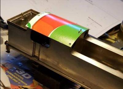

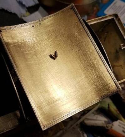
 Next vents, rain-strips and planking…….
———————————————————————————————————
Nick Dunhill - Jan 13, 2018 at 5:24 PM
….the 'perimeter only' lower roof portion has been infilled with veneer. The top of the roof now has vents, rain strips, etc.
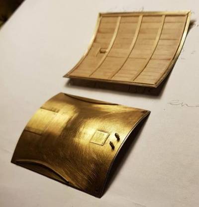
 Does anyone have any advice on how to stain the wooden strips? I thought I'd stain them (and the wooden locker) and WH can just varnish over them later…….
———————————————————————————————————
Jim Snowdon - Jan 13, 2018 at 5:59 PM
With wood stain? I know it does seem the obvious answer, but wood is wood. The home brew equivalent is to make up a stain from acrylic paints and isopropyl alcohol.
After that, it depends on whether you want brand new ex-works condition, or in service condition.
Jim
—————————————————————————————————–
DLOS - Jan 13, 2018 at 9:45 PM
Nick, On the few occasions that I have done this, I have used shellac on the natural wood and then later I have varnished it, along with the other parts of the model. David
———————————————————————————————————–
paul copsey - Jan 14, 2018 at 12:18 PM
Hi Nick , i use a brand of spirit based marker pens called Copic . Many many shades .
Cheers Paul
————————————————————————————————————–
Nick Dunhill - Jan 21, 2018 at 10:47 AM
…..I have added the sand boxes, lids and operating linkages and rods.
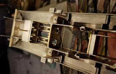
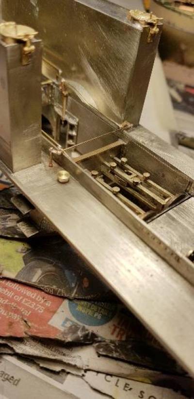
 The linkage is all made from rod and telescoping tube.
I'm going to make the boiler next and hope someone can help with a bit of information. I am looking for a photo or drawing that shows the way that the NER joined the boiler clothing. There appears to be a line of screws along the top of the boiler, so presumably one end of the boiler clothing is joggled and overlaps the other. The screws then hold the overlapping joint together. Question is, is the panel join centered or is the line of screws along the centre (or somewhere in between even.) Are the screws to the left or right of the join? I'm sure all locos built at Darlo would be the same, so a pic of any NER
engine would tell me what I need to know. Question the second. Is the front of the firebox lagged? Or can you see the firebox stays in the front of the firebox under the boiler?
Thanks in anticipation……..
END OF WHITBY TANK 2.
————————————————————————
START OF WHITBY TANK 3
———————————————————————–
Nick Dunhill - Jan 24, 2018 at 4:38 PM
….basic boilers. The boilers were rolled from 111 x 125.5 mm sheets of .25 mm nickel silver. (Actually it's nearer 110 mm but best cut to size as required.) Front and rear formers were cut out as the drawing below. The front former was soldered in place using cable ties to hold the cylinder tight, join at bottom. The boiler join was tacked together at this stage. Cuts were made in the bottom of the boiler to allow the rear to be unrolled and formed into the firebox clothing. The cuts were 47.7 mm from the rear and approx 15 mm up from the bottom of the sheet, adjusting as required, until the rear former is a good fit. The centre line of the top of the boiler was scored to represent the plate join, and holes for screws pre-drilled. The rear former was also scored with a centre line which was aligned with the centre of the top of the boiler.

 Although strictly a vanity project, as it can't be seen, I elected to extend the firebox sides downwards to meet the ashpan, which is attached to the chassis. Dimensions of the pieces used is shown above. I also added a firebox lower front (23 x 24 mm.)


 Next boiler bands, washout plugs etc…..
————————————————————————————————————–
Nick Dunhill - Jan 25, 2018 at 7:41 PM
…thought this might be of some interest. This is how I have done the angle iron infill between cab front and smokebox. I scored round the rear of the firebox and cut out a piece of brass bigger than the profile of the rear. That was soldered on and a narrow brass strip attached round the firebox to complete the illusion. Not my best finish ever on the invisible bits!! I added some washout plugs to the firebox front.
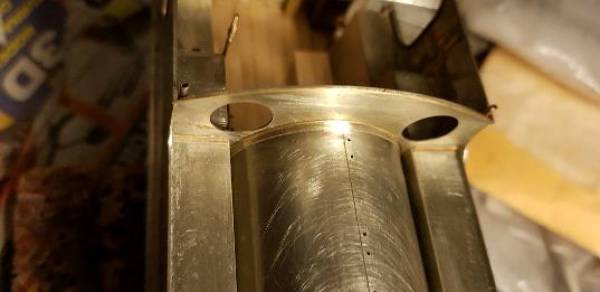
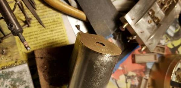
 Boiler bands next…………..
————————————————————————————————————–
ChrisSimpson - Jan 25, 2018 at 8:04 PM
Hi Nick, I did similar on my Achilles class, but I didn't need to cut a curved part. I used a strip of straight brass, annealed it, and managed to form it to a curve in the 'wrong' plane. Saved a bit of time. I didn't take any piccies though.
Very much enjoying this build.
Chris
——————————————————————————————————-
Tom Burnham - Jan 25, 2018 at 9:17 PM
This is what the interior of a NER cab looked like, showing the varnished wood roof planks and the imitation wood finish to the sheet metal cab sides.
Tom.
NER Class M 4-4-0
 NER 'Aerolite' 2-2-4T
 ====
Nick Dunhill - Jan 26, 2018 at 1:06 AM
Thanks Tom. My hero……
——————————————————————————————
Nick Dunhill - Jan 26, 2018 at 5:12 PM
….boiler bands!! Takes a couple of hours but worth the effort I think.
I have run out of boiler band material. Eileen's Emporium used to sell 1.5 x 0.15 x 150 mm strips, ideal for boiler bands. Now they only stock 1.5 mm strip in 0.2 mm thickness. Anyone know of a source of 0.15 mm stuff, or with a guillotine who could cut me some? Thanks in anticipation.
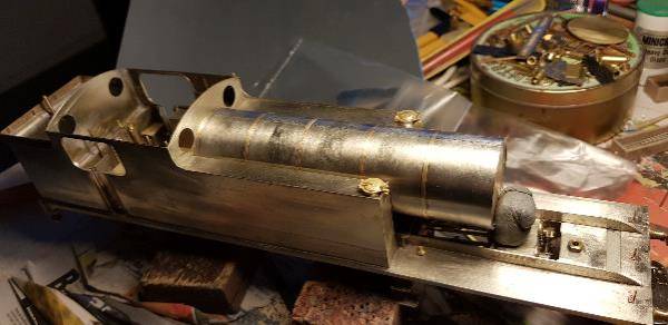
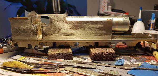
 —————————————————————————————————-
PeterT - Jan 26, 2018 at 7:09 PM
Good evening Nick.
Amberly Services sell Phos.Bronze Strip 1.0mm wide x 0.15mm thick
2 pieces each 300mm long £4.00
They will be at Bristol on Sunday
Regards PeterT
—————————————————————————————————-
Nick
I can do 1.0mm wide x 0.1mm thick at longer lengths than that and cheaper prices. I bought a job lot of it and I also have the same width but 0.3mm thick in Nickel silver too.
I have personally found the phosphor bronze size to be ideal for boiler bands.
A while back I advertised it on flea-bay but I have not put anything on there lately.
David A
———————————————————————————————-
Nick Dunhill - Jan 31, 2018 at 5:27 PM
…..I've made a skeleton of the smokebox. The sealing ring for the smokebox door was put on the front and then a tubeplate etching (cheers JB) added to the rear. I must say that first you should identify which smokebox you need. Mine is the original flat fronted one, but most will make the later version, and all parts are present. The front and rear formers were fitted to a 'floor' measuring 26 mm wide and 20.6 mm long to give an overall length of 21.6 mm (as measured off the GA.) Beware if you follow my drawings on Flickr as the smokebox GA shows the short lived long firebox (intended to accommodate superheating which was never fitted.) A secondary floor was added using 3.5 mm raisers and the sloping protector plate added. I assume this was to prevent ash and clinker settling on the cylinder block casting. The front of the firebox was cut away at the bottom, as prototypical, to clear the cylinder fronts. Finally some temporary spacers were added to strengthen it all up. I will add the door, and all the internals (blastpipe etc.) and fit the wrapper afterwards.
—————————————————————————————————-
PeterT - Jan 26, 2018 at 7:09 PM
Good evening Nick.
Amberly Services sell Phos.Bronze Strip 1.0mm wide x 0.15mm thick
2 pieces each 300mm long £4.00
They will be at Bristol on Sunday
Regards PeterT
—————————————————————————————————-
Nick
I can do 1.0mm wide x 0.1mm thick at longer lengths than that and cheaper prices. I bought a job lot of it and I also have the same width but 0.3mm thick in Nickel silver too.
I have personally found the phosphor bronze size to be ideal for boiler bands.
A while back I advertised it on flea-bay but I have not put anything on there lately.
David A
———————————————————————————————-
Nick Dunhill - Jan 31, 2018 at 5:27 PM
…..I've made a skeleton of the smokebox. The sealing ring for the smokebox door was put on the front and then a tubeplate etching (cheers JB) added to the rear. I must say that first you should identify which smokebox you need. Mine is the original flat fronted one, but most will make the later version, and all parts are present. The front and rear formers were fitted to a 'floor' measuring 26 mm wide and 20.6 mm long to give an overall length of 21.6 mm (as measured off the GA.) Beware if you follow my drawings on Flickr as the smokebox GA shows the short lived long firebox (intended to accommodate superheating which was never fitted.) A secondary floor was added using 3.5 mm raisers and the sloping protector plate added. I assume this was to prevent ash and clinker settling on the cylinder block casting. The front of the firebox was cut away at the bottom, as prototypical, to clear the cylinder fronts. Finally some temporary spacers were added to strengthen it all up. I will add the door, and all the internals (blastpipe etc.) and fit the wrapper afterwards.


 [img]https://farm5.staticflickr.com/4659/39108853645_f188b6ff4f_k.jpg[/img]
Of course if you're not modelling an opening smokebox door and haven't fitted the cylinder fronts (more vanity projects!) then you can skip many steps here. Internals next……
———————————————————————————————————
Nick Dunhill - Feb 6, 2018 at 5:28 PM
….bits of smokebox detail. I took measurements from my Flickr account here;
https://www.flickr.com/photos/144381574@N05/albums and bashed them into the calculator here;
http://craig-russell.co.uk/demos/cone_calculator/ and cut out paper templates to make the petticoat pipes. They're cut from thin brass, and formed round a small drill shank. I got lucky and found some driving wheel spacers that were the perfect size for the bottom of the mesh cylinders, cut to represent the spark arrestors. I cut out some door locking crossbeams and added a representation of the steam pipes.
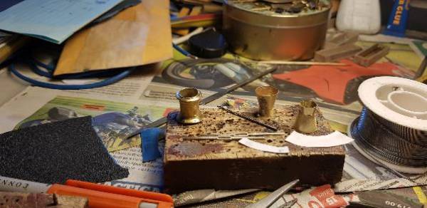
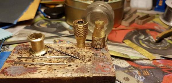

 I'll finish off when the blast pipe castings turn up from Laurie Griffin!…..
———————————————————————————————————–
Bob Alderman - Feb 6, 2018 at 10:06 PM
Nick
Whence came the gauze/mesh around the petticoat pipe? Another tea strainer?
Bob
——————————————————————–
Nick Dunhill - Feb 6, 2018 at 10:22 PM
Hi Bob
It's fine oil filter mesh. Can't remember where it came from, but I think Eileen's Emporium sell it.
Nick
————————————————————————————-
Nick Dunhill - Feb 12, 2018 at 5:58 PM
……so this post is a bit of a catch up. I've been waiting for odds and sods to turn up, so have been moving on to other things without finishing what I was doing and it was all starting to get a bit disjointed. I fettled boiler fittings, chimney, dome and safety valves and then my etchings arrived, yay.

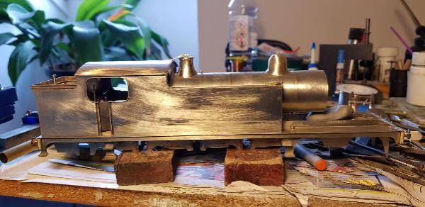
 These mud hole covers were a bit vexing to fit. They required spinning in a mini drill to clean up, and then were awkward to position.
 Nice brass window frames, window guard bar rings and handrail brackets on an etch.

 So I amused myself for a couple of hours mounting tapered handrails with the brackets.
Next watch as I descend into madness making the rear cab window protection bars……
————————————————————————————————————
Robson17023 - Feb 13, 2018 at 10:33 AM
I never feel inadequate looking at the work of the experts on this forum as I know at my time of life I will never gain the skills they have. I am inspired to try to improve my models knowing that I am working within my own capabilities and do get a lot of satisfaction from what I do.
So a big thank you to all the contributors, too many to name for giving me an insight into your world.
Eric r.
———————————————————————————————–
Nick Dunhill - Feb 16, 2018 at 5:46 PM
….right, I have now sorted out the cab windows. The windows are a sandwich of an outer round frame and an inner bigger frame, sandwiching a disc of clear plastic. A fellow modeller has a 10 mm punch and has offered to lend it me to punch out plastic window discs, so more of that later. I would advise that the outer round frames have the cusps filed off and the window apertures in the cab front and rear are dressed with a half round file so that the frame sits nicely inside it. The plain outer frame sits within the aperture when finally fitted up. The inner frame has a small square of brass fitted to it to represent the open position bracket, and thin wire to represent the chain that holds a pin to lock the window open on the bracket. A similar bracket has been made for the underside of the cab roof. This locates the window in the fully opened horizontal position, NER round cab windows are hinged at the top.
 The etch includes a guard bar ring with half etched holes showing drilling locations. The holes were drilled out 0.4 mm (drilling and addition of bars were done whilst the part was still in the etch for ease of handling,) and the bars (44 for 4 frames!) were cut and bent from 0.376 mm rod. I thought this would be a nightmare, but once I got my eye in it was quick and easy, and quite therapeutic. A suitable width of 0.5 mm thick sheet was slipped between the bars and the ring, and the bars soldered in place on the rear. Soldering one end first allows a bit of spacing adjustment with some tweezers and then the other ends of the bars were soldered up.
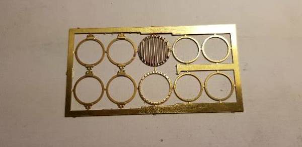
 The trickiest bit was actually soldering the finished bar assembly to the cab. It has to be centered on the aperture with the bars vertical. I used Blutac to hold it while checking.
 Hopefully some smokebox progress next….
————————————————————————————————————–
Nick Dunhill - Feb 20, 2018 at 5:36 PM
….just a little finishing strip. The Ws had a brass cover between the boiler and smokebox (it hid some bracketing) which of course in NER days was polished. Mine is made from 1 x 1 mm square brass bar curved in my rolling bars and with one corner radiused off. It was made oversize and cut to the correct circumference, you have to manipulate it a bit to fit the end of the boiler snugly.
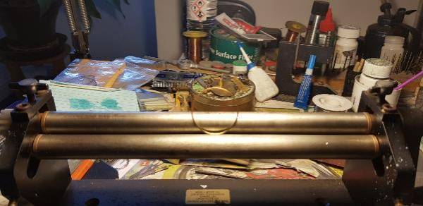

 Next more smokebox work……
————————————————————————————————————-
Nick Dunhill - Feb 28, 2018 at 8:40 PM
…..I thought it would be a good thing to finish the tank fronts. Footsteps were made from waste strip and attached. The balance pipe looked a bit more tricky. The elbows at either end were made by cutting a 90 deg wedge, 2/3 way through a section of 2.5 mm rod. The rod can be then bent to a right angle and soldered up, no annealing needed. The round flanges were made by sandwiching two thin washers together on a short bit of 2.5 mm rod. The washers were spun in a minidrill and filed to the correct diameter. The resulting flange was drilled and furnished with screws from the Scale Hardware range. The other joining flange was cut from 2.5 mm ID thin walled tube. The balance pipe was carefully fashioned from more 2.5 mm rod, and the finished pipe carefully assembled on the model. It was VERY tricky.
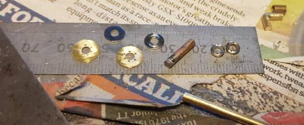
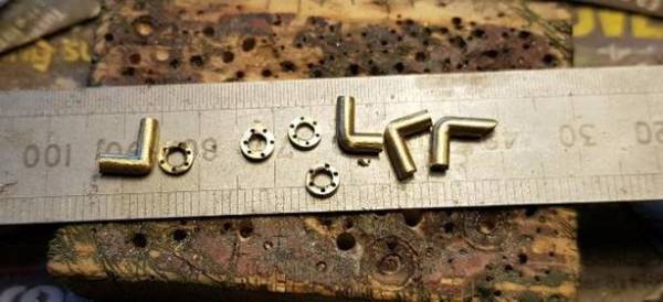


 Next, Kettering………..
———————————————————————————————————
Bob Alderman - Mar 2, 2018 at 1:07 PM
Nick, a thought. Should there be a hole in the front of the roof to access the safety valve relieving lever?
Or was there a link into the cab to pull down on it?
Bob
———————————————————————————————————
Tom Burnham - Mar 2, 2018 at 5:08 PM
On the General Arrangement drawing there is a handle attached to the end of the safety valve lever that drops through an aperture in the roof.
Tom.
 ———————————————————————————————————-
Nick Dunhill - Mar 4, 2018 at 8:04 PM
Sorry yes the lever will sit above the cab roof and there is a hole and drop handle. Does anyone have a pic of a Ramsbottom safety valve from the top?
———————————————————————————————————
Tom Burnham - Mar 6, 2018 at 6:05 PM
Nick,
If you search for Ramsbottom safety valves in Google images there are numerous examples of CAD drawings showing the valves from above like these: -
https://www.google.co.uk/search?q=ramsbottom+safety+valves&rls=com.microsoft:en-GB:IE-SearchBox&dcr=0&source=lnms&tbm=isch&sa=X&ved=0ahUKEwjKyKf7n9jZAhXMKMAKHUClD6cQ_AUICigB&biw=1580&bih=756
The NER pattern valve shown on the General Arrangement drawing differs from the U shaped examples shown but the view from above will be similar.
Here's a view from above of a NER Ramsbottom safety valve cover and, unlike the Laurie Griffin casting which has the top blocked off, the safety valve would be visible in its entirety so you may wish to amend the casting accordingly.
Tom.
 ————————————————————————————————————–
Nick Dunhill - Mar 7, 2018 at 10:27 AM
Thanks for that Tom, I think! Will amend away…. I sat looking at the top of the casting at Kettering and thought 'surely some mistake here' and was right.
—————————————————————————————————-
Nick Dunhill - Mar 12, 2018 at 9:19 PM
….following on from Tom's picture above the Ramsbottom SV has been amended. I opened up the top of the cover casting with rotary files and burrs in a mini drill and made a proper Ramsbottom safety valve using the top of the casting supplied. I think it looks a bit better.
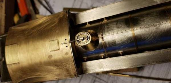

 I also added the blast pipe, spark arrestor and petticoat pipe to the smokebox with some more piping for the blower and Westinghouse pump (plus other odds and sods.)
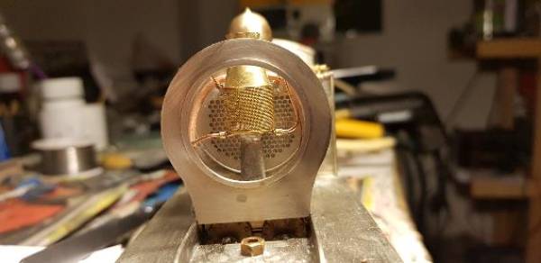
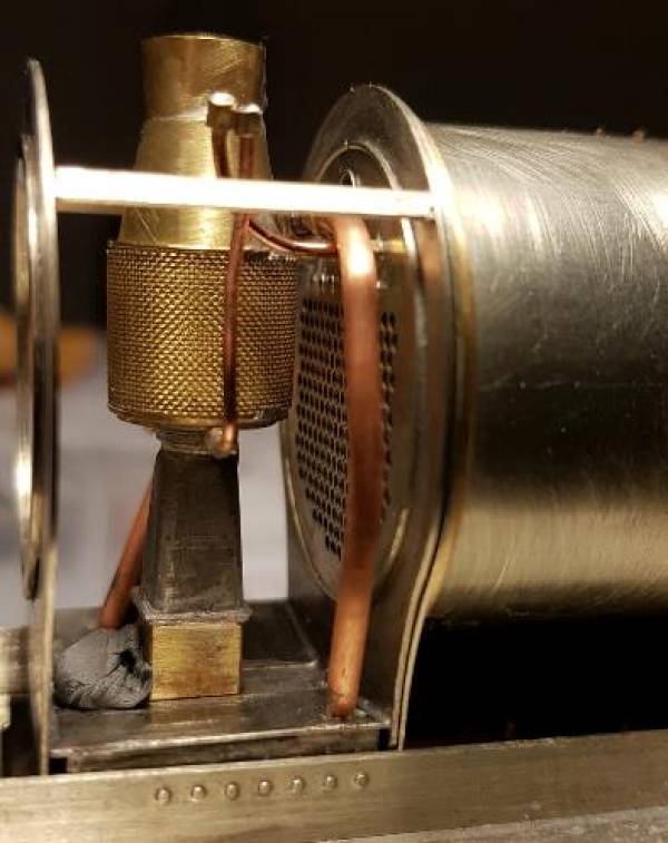
 I now await the arrival of a 3D printed smokebox door to complete the smokebox and then boiler…..
—————————————————————————————————————
Bob Alderman - Mar 13, 2018 at 3:25 PM
Nick
When I wondered about the hole in the roof I didn't think it would lead to so much work! However… excellent.
Bob
——————————————————————————————————–
Nick Dunhill - Mar 13, 2018 at 6:58 PM
Well Bob, best to sort it out. It looks a lot better now.
————————————————————————————————————–
Nick Dunhill - Mar 13, 2018 at 8:46 PM
…Thanks for the encouraging words guys. I have made some brass fittings to accommodate the copper pipework on the cylinder block/smokebox rear. I think the bigger brass castings are anti-vacuum valves and the long copper pipes are the high pressure oil/steam mix for the cylinders and valve chests. The pipes originate from the atomiser in the cab.

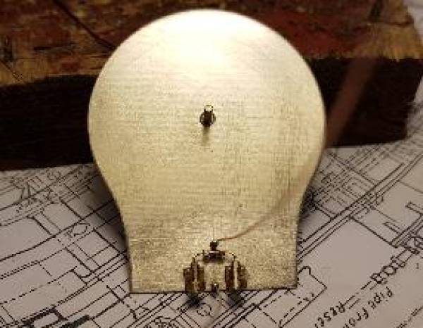
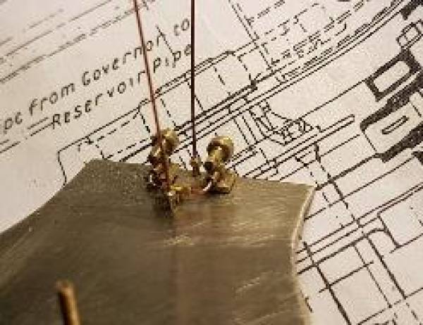
 Tomorrow will be a nice day so no modelling, I'm off out on me motorcycle and the Ws can wait…….
————————————————————————————————————–
Nick Dunhill - Mar 16, 2018 at 5:45 PM
….I have made some lubricator pots for the Ws as the usual casting suppliers had none.
The first ones are kiln shaped on an elbow. The pots were shaped in a mini drill and mounted over some bent rod, and fixing plate was added.
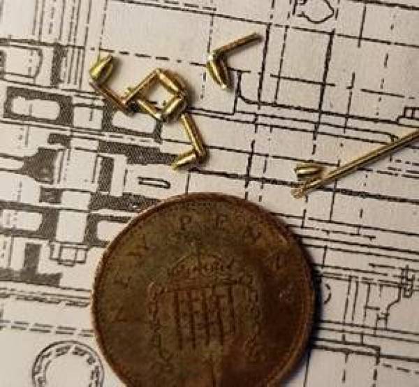
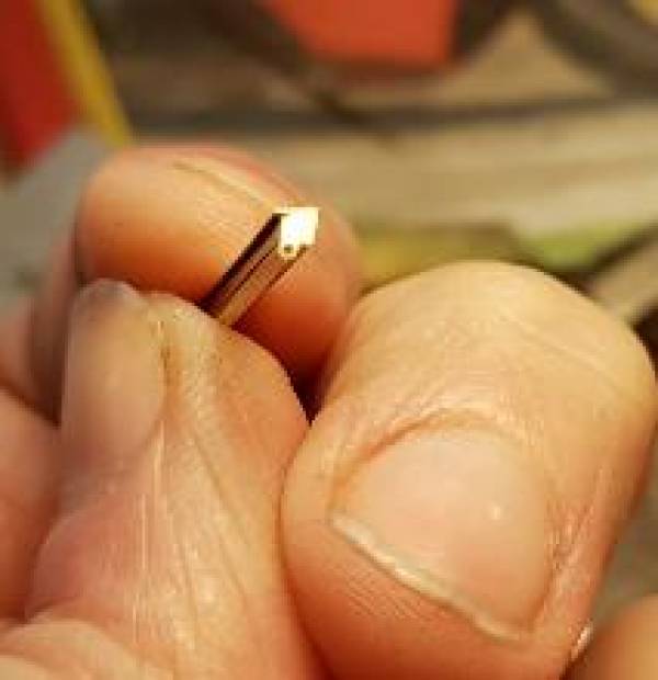
 The second lubricators are more conventional slopey rectangular ones but with a stop valve and have one outlet. The bodies were made by filing a chamfer on one edge of some square brass bar and planting on some strip for the lid and tube for the valve. A hole was drilled for a copper outlet pipe and a brass ferrule, and the handle added. The pot could then be cut to the required length and a mounting plate added, made from waste brass boiler band material. On the real thing these feed oil to the bogie slides. Each one is made from 8 pieces, madness!

 Some over complicated valves next……….
——————————————————————————————————————
Bob Alderman - Mar 16, 2018 at 8:43 PM
Nick
How do you do it? Making multiples all the same.
I can usually make one, but another five the same… never.
Well done.
Bob
————————————————————————————————–
Nick Dunhill - Mar 17, 2018 at 12:16 PM
Bob, you didn't see how many rejects there were!
————————————————————————————————————
Nick Dunhill - Mar 18, 2018 at 6:29 PM
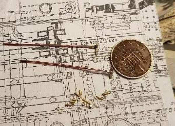
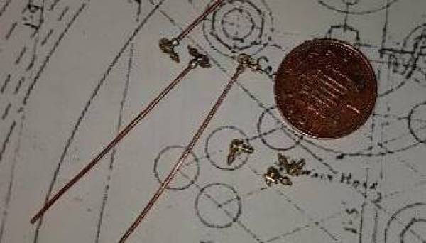
….this one's just a quickie, I have made a couple of valves that sit atop the smokebox. One is the blower control and the other a steam control for the Westinghouse pump. Both have had their bodies shaped from rod with files in a muni drill. The fittings are made from telescoping tube, the nuts are tube filed into a hexagonal profile. The latter is easy to do in my pin vise as it has a hex chuck.
 Window frames next….
——————————————————————————————————————
RobPulham - Mar 19, 2018 at 4:21 PM
Hi Nick, a question if I may on your mini drill?
Do you have a mini drill with a chuck or do you use collets?
I ask because I have a Dremel battery mini drill which has a Dremel chuck and although it seems fine when drilling holes, if I try to turn anything with it, whatever I turn is distinctly lopsided. I have heard people mention that collets run a lot more concentric and knowing what you achieve with yours wondered what you are using.
——————————————————————————————————
StephDale - Mar 19, 2018 at 7:45 PM
Rob,
The Dremel collets are very good in my experience and much more accurate than their chucks. The Proxxon/Rohm chucks is pretty good, just in case anyone reading this has Proxxon tools….
Steph
——————————————————————————————————–
RobPulham - Mar 19, 2018 at 7:48 PM
Thanks Steph,
I have a Proxxon chuck on my Proxxon mini pillar drill and I haven't seen any issues with that.
I have just invested in a second battery mini drill (£20 from Lidl recently) which came with collets so I intend to try them. I am sure that I still have the collets for my Dremel but they are in a safe place:rolleyes:
—————————————————————————————————-
StephDale - Mar 19, 2018 at 7:54 PM
Rob,
If your Proxxon TBM220 has the dedicated Rohm chuck, it's the good one. I use mine down to 0.2mm without problems, which makes it exceptionally accurate for a conventional chuck.
Quite how good your collets are going to be in a £20 mini drill is anyone's guess, but they might be worth a try. The problem is likely to be getting them to tighten up on drills which between the collet sizes. The Dremel ones are very flexible as they're made from (anodised) alumium I think; they also wear but seem to remain accurate enough for our purposes throughout their life.
Steph
——————————————————————————————————–
Nick Dunhill - Mar 20, 2018 at 9:14 AM
Mine's a Mini Craft drill with a chuck. Cheap and cheerful!
———————————————————————————————————-
Nick Dunhill - Mar 20, 2018 at 10:41 AM
The chuck's a bit worn now so won't hold anything less than a 0.4 mm drill or rod. Sooner or later I'll knacker the bearings though using it as a laithe or mill.
——————————————————————————————————–
RobPulham - Mar 20, 2018 at 5:19 PM
Thanks Nick,
The luck of the draw I guess, my probably more expensive dremel chuck doesn't quite run true and yet your cheap and cheerful one does:confused:
—————————————————————————————————–
Nick Dunhill - Mar 20, 2018 at 8:01 PM
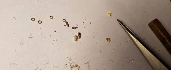
…so to the last of the lubricators. This one is for the valve guides and is mounted on the motion bracket between the slide bars. It is made from tube, rod and a 4mm handrail knob. A big thanks to DLOS who explained how to make the knurling on the knurled rings of the can.
 Then on to the window frames. The frames are a circle of transparent acetate to represent the glass sandwiched between the brass outer and inner frames, a bit like the real thing. They are a push fit into the apertures in the cab. A massive thanks to Kevin Wilson for stamping me out the plastic discs.

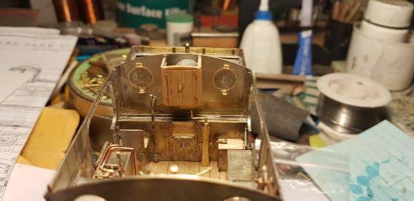
 Finally for this post I'm after a bit of help. Does anyone out there have a couple of etchings (or similar, maybe a left over backhead handwheel) they could spare me for the smokebox door handle wheels?
 It's about 4.6 mm in diameter and I want to drill and tap the centre so I can make the handles work prototypically….
—————————————————————————————————————-
Nick Dunhill - Mar 21, 2018 at 9:02 AM
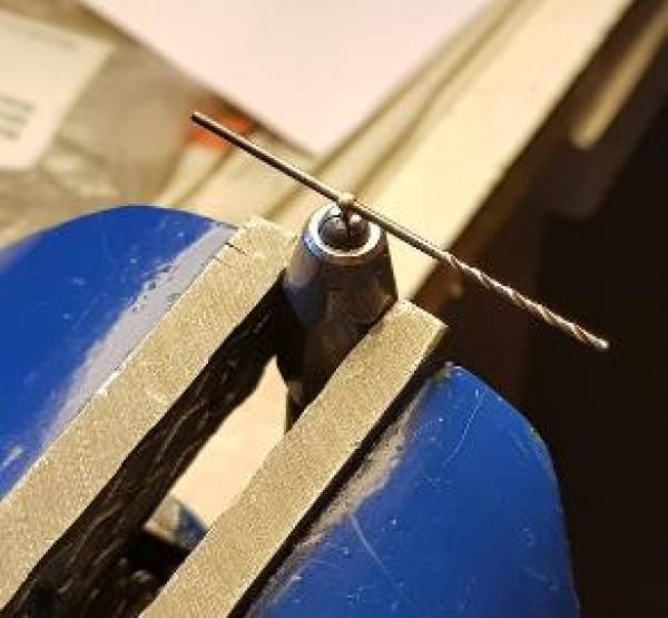
…It is a solid wheel, and I think I'll have to fabricate something. So Jim, how to cut a square in the inner handle. Pictures are pretty self explanatory I think, but it's drilled out to 1 mm to accept a 1 mm square rod and the corners are carefully cut out with a piercing saw.

 Now to make a hand wheel….
————————————————————————————————————
Nick Dunhill - Mar 21, 2018 at 10:02 AM
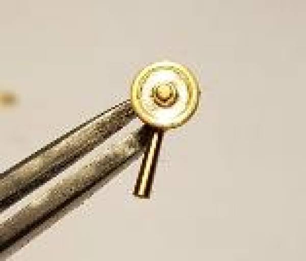
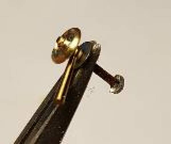
…hand wheel made from threaded tube middle, a washer and a slice of thick walled tube.
 ——————————————————————————————————–
Nick Dunhill - Mar 21, 2018 at 6:17 PM
the finished item, with a dart made from 1 mm square rod.
 Next we get a 3D printed smokebox door…..
—————————————————————————————————————
RobPulham - Mar 21, 2018 at 7:06 PM
Superb Nick,
Is the handle (that you made the 1mm square hole in,) bought in or home made?
—————————————————————————————————————-
Nick Dunhill - Mar 21, 2018 at 7:33 PM
Laurie Griffin gave them to me, they're turned smokebox door handles. Not sure who I could get some more from and I've used them all up now. Let me know if you find a supplier. If you're not bothered about the handles working Laurie sells cast ones as does Dave at Gladiator.
———————————————————————————————————
If you have a lathe, making a smokebox door should be possible by turning the curved front part on the face of a bar, then parting off (leaving a flange for location on the smokebox - provided the curve is a portion of a sphere. Rather more difficult if it is some more complex shape.
David
———————————————————————————————————-
DLOS - Mar 22, 2018 at 9:21 AM
Pressing is not too difficult. Find a suitable ring (eg an outer race from an old ball bearing, or some such) and clamp a piece of 10 thou brass between it and a sheet of hardish rubber in the vice … and squeeze. Works every time for me … except when it's a more complicated shape, with a reverse curve, in which case see here:
http://www.davidlosmith.co.uk/GWR1361Class.htm#Smokeboxdoor
but that was unusual, in my experience.
David
 —————————————————————————————————————-
paul copsey - Mar 22, 2018 at 11:12 AM
Hi Nick , a friend showed me a trick of how to make a smokebox door . It needs a nice soft-ish plastic and for that I use some old square plastic trunking used for electrical cables .Use a compass to mark the diameter of your smokebox and then cut roughly to size. Drill a hole the size of your handwheel mounting bolt using the centre point from your compass and then use a bolt the same size along with a washer back and front and lock up with a nut . Mount the whole lot in a drill chuck and then mount in a vice , then use files to shape a suitable curve on the face , I do this in a lathe but it works in a drill . When you're almost finished take the whole lot apart and finish with wet & dry or your favorite sanding paper remembering to blend in where the front washer was .
Good luck , cheers Paul
—————————————————————————————————-
Nick Dunhill - Mar 22, 2018 at 3:30 PM
Thanks everyone. If I hadn't got a 3D printed one in the post I'd certainly be having a go at making one. Hope I can make it look ok.
—————————————————————————————————-
RobPulham - Mar 22, 2018 at 6:43 PM
Thanks Nick,
The ball on the end looks to be a bit bit bigger than on most that I have seen included in kit's that I have. If you had tried to open the hole out to 1mm and square it off there wouldn't have been much left.
———————————————————————————————————
RobPulham - Mar 22, 2018 at 10:09 PM
Hi Nick,
Just by chance I had a look in my Warren Shephard N2 kit this evening looking for something else and noted that the turned dart looks to be much like those that you used with a larger ball end. The only difference is that the shanks are parallel whereas the ones in your pictures look tapered towards the ball.
—————————————————————————————————-
Nick Dunhill - Mar 27, 2018 at 5:58 PM
….and on to the 3D printed smokebox door. This is a completely new departure for me, and I was pleasantly surprised by the moulding. It is accurately made and not too 'layery' as are some other mouldings I have seen. It did require a bit of fettling as it had a slightly uneven surface, but it took minutes going up the grades of waterproof abrasive paper as opposed to hours. I might blow some primer over it to check the surface before it goes off to Haywood Towers (what sort of primer Warren?)
The hinge brackets were way to thin to be drilled for a hinge pin but this proved to be a blessing. I cut 4 lengths of 0.8 mm OD x 0.5 mm ID x 0.8 mm tube to act as bearings for the 0.45 mm hinge pin. The bearings were threaded on a 0.5 mm drill and tacked on to the underside of the 'ears' of the hinge bracket with minute amounts of superglue. This process ensured that the pin would be in the exact place relative to the door and sealing ring. I'm willing to bet that I'd have never done this successfully trying to drill out a thicker hinge bracket. Inevitably the hole would be in the wrong place or the drill would have wandered or I'd have broken something off! The drill was withdrawn and the tiny bearings encased in epoxy resin on the underside of the printed brackets. This took a couple of applications to get the required thickness and great care was taken not to glue up the ends of the bearings. After the epoxy had cured overnight it was easy to sculpt the correct shape hinge brackets with a fine rotary sander.
The rest, as they say, was child's play. Mark holes for the other hinge brackets on the smokebox front, and make the brackets from carefully drilled 1 x 1 mm brass rod. The door was united with the handles and locking bar (see previous posts), and, when correctly positioned, the brackets and bar soldered to the back of the smokebox front.


 I think the slight flexibility of the plastic door hinge brackets will help it withstand a minor accidental bop better than a white metal item, and also the door is much lighter and exerts less stress on the hinge. Winner winner tofu dinner! Next the dreaded smokebox wrapper!………..
Just realised that the blastpipe/spark arrestor/petticoat pipe assembly can't be shoved through the front of the smokebox with the locking bar in place. D'oh, thinking cap on…….
———————————————————————————————————–
DavidAtkinson4172 - Mar 28, 2018 at 12:48 AM
Nick
They didn't in real life either. The locking bar was a removable item to allow for maintenance.
David A
———————————————————————————————————–
Nick Dunhill - Mar 28, 2018 at 7:41 PM
…..here it is all done. Another problem solved, cheers all.
 Maybe should have taken the pic before washing it!!
———————————————————————————————————–
Nick Dunhill - Apr 10, 2018 at 10:35 PM
…right, back from hols so on with the show. I have cut out the smokebox wrapper and shaped it using rolling bars. For those out there making up Mick and my etches the pieces I cut out were 106.5 x 21.5 x 0.25 mm. The wrapper is lined up with the chassis tops on one side (scored lines needed here) and tacked in place. It was finally checked on the loco body and soldered up. A bit of filing up is required (I use a sanding disc in a mini drill and final finishing by hand) and then the rear plate was positioned and soldered in position.
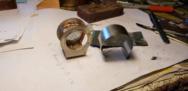

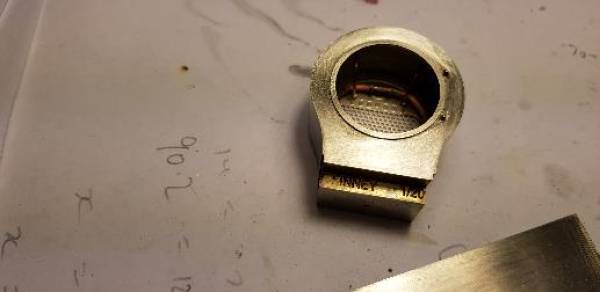
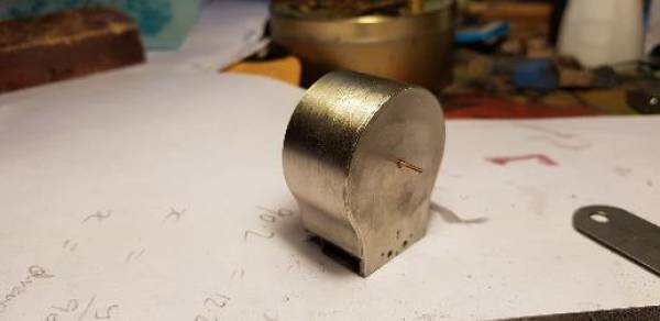
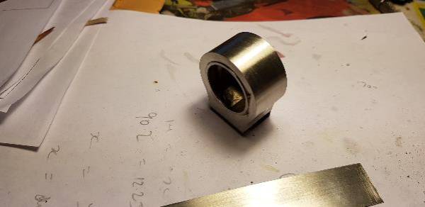
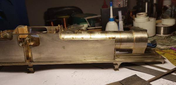
 A quick check with the boiler showed a midges-dxxx needed to be taken off the length of the boiler at the firebox end. This was probably because I tacked an oversize plate to the rear of the boiler to represent the vertical section of the angle iron between boiler and cab.
Next I drill an opening for the chimney and do a 'ship in a bottle' thing to get the blast pipe/spark arrestor/petticoat pipe in the smokebox front…..
————————————————————————————————————
Martin Long - Apr 11, 2018 at 4:44 PM
Nick
Awesome stuff from you (I would expect no other). Your pictures of the smokebox indicate that you too have had an issue which I often meet. I refer to the wrapping of the smokebox over the formers where there is a rather tight curve right at the base. Your picture shows the wrapper being slightly proud of the former. How do you get this to flush up nicely? I have tried the Alderman method of wrapping wire which works if a fully circular smokebox is involved but that is not the case here. Also I have found that the work gets too hot to hold when soldering and so the wrapper cpmes off somewhere else! Most frustrating. How do you do it please?
Martin L.
———————————————————————————————————
Nick Dunhill - Apr 11, 2018 at 7:16 PM
Hi Martin
I think the picture is tricking your eye a little. There is no gap between the wrapper and former, what you can see is a little solder that has flowed. The wrapper was made fractionally wider than the formers and sanded back flush after soldering, but soldering up already flush to one former.
My method is to carefully form the wrapper in some rolling bars trying not to curve the ends. Offer it up to the formers and mark with a pen where the reverse curve is and bend those round a suitable sized bar. When to former is approximately correct I spend some time making it a close fit by hand manipulation. This takes a lot of time and it should be the exact curve if possible, if too tight it always bulges out somewhere else, and usually on the reverse curve. This makes it much easier to solder to the formers and aids positioning. I use 0.25 mm nickel silver for the wrapper so it is easy to manipulate without distorting. It is difficult to bend a curved surface straight without some distortion.
Hope this helps, I'm afraid there's no dodge! Oh, and solder quickly so you don't burn your hands, and I use emery to try and insulate my fingers.
Nick
———————————————————————————————————
Nick Dunhill - Apr 12, 2018 at 6:37 PM
….wey hey here's one of my finished smokeboxes, not as difficult as I thought.
Now you see it,
 Now you don't,
 Next attaching a boiler…
——————————————————————————————————-
Nick Dunhill - Apr 17, 2018 at 7:19 PM
……I have attached one of the smokeboxes to it's loco. I lined up the boiler and smokebox using paper wedges and a tapered file and to get the right alignment then tacked the two together.
 Then the rest of the soldering could be done with the assembly off the rest of the body. I added the polished brass joint cover, the first boiler band, a cleat and the last few screws along the top of the boiler clothing.
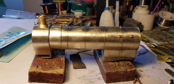
 So that's all the main structures of the loco completed. Just a ton of detail to go!
you can see the valve chests for one last time before I make a cover! It captures the look of the prototype I think.
 Valve covers and control rods next……
—————————————————————————————————-
Nick Dunhill - Apr 17, 2018 at 7:55 PM
I have a pipe and rod that shows the plumbing under the footplate and between the frames and I thought I'd have a go for a bit of fun. It's got a few tanks and runs of pipes and a couple of valves. As for the upperworks there's just the control valves for the Westinghouse pump and blower, the Westinghouse pump and plumbing, the bonnet and the straps linking the boiler to the water tanks.
Sorry, no distress intended.
————————————————————————————————
Nick Dunhill - Apr 23, 2018 at 6:49 PM
….This is a note to the half dozen or so of you out there in GOG land making one of these locos. My boiler is screwed to the cab front and the smokebox to the section of footplate under it. You may find you have to trim the end of the boiler so that the rear of the smokebox aligns with the cylinder heads and is vertical. Mine were cut to the dimensions in a previous post and needed 0.2 - 0.3 trimming off the end. This is presumably to compensate for planting a piece on the boiler rear, up against the cab, to represent part of the angle iron present between firebox and cab.
I had to plant a very thin strip below the smokebox wrapper on one side (I started soldering the wrapper on the other side at the top of the frames) to bring it down to the top of the frame. So maybe the length of the wrapper should be increased by 0.3 mm, or a bit more to trim back?
This one is yours Dave. Finally got round to sorting yours out after a week without progress. I had to fit some guttering (wooden) to our offshoot kitchen, and took advantage of the good weather for painting…..
 ———————————————————————————————————–
Nick Dunhill - Apr 25, 2018 at 6:11 PM
….well I made the cover to fit into the half etched recess and summat was definitely up! A bit of a measure revealed the half etched rectangle to accept the bonnet to be in the wrong place! It should start where it ends.
 Mercifully some of the waste on the 0.4 mm thick etch is the correct thickness (check with the depth gauge on your calipers.) Sorry about that chaps but at least it's an easy fix, even easier if you do it at the beginning!
 The bonnet was formed round a 5 mm drill, top curve first then the bottom one. I tweaked it by hand to match the former present in the etches. I scored the join, added hinge pins and an upstand with handle. It was a bit tricky to make fit properly but worth the effort.

 Next the interesting brackets that connect the tanks to the boiler…..
—————————————————————————————————————-
Buckley10339 - Apr 25, 2018 at 6:33 PM
Nick,what did you use for the rivets/bolts on the top of the boiler clading.This morning i did them on my DJH V1/3 boiler using EDM plastic rivets 15 of them and they look a fair representation rather than the .4mm wire that is shown on the instructions that DJH show.I have allso just done on a Thompson A2/2 boiler the same but with smaller ones that are very closely spaced only about 2mm apart.There are 39 on the Thompson loco so the small ones seem to be a better bet -your thoughts on this would be appreciated .
I have used the EDM plastic rivets on seven locos now to represent the bolts /rivets that hold the cladding together and find them quite good.
Pat.
—————————————————————————————————————
Nick Dunhill - Apr 25, 2018 at 8:37 PM
Hi Pat, they're 0.6 mm simulated screws from the Scale Hardware range at Model Motorcars Ltd
https://model-motorcars.myshopify.com/collections/small-parts-hardware
I think boiler clothing was always secured along the top with set screws rather than rivets.
Nick
——————————————————————————————————–
Nick Dunhill - Apr 26, 2018 at 7:12 PM
 So, I have had a chat with Mick (etchings designer) and the recess was planned. He thought it was easier to form the S shape with a longer strip for the bonnet and drop it into the recess, also easier to blend in. The design was based on a bonnet as the red line and I did the blue route. However same end result.
————————————————————————————————-
Nick Dunhill - May 4, 2018 at 6:22 PM
…..I have made more progress on the boilers. I have cut holes in the boiler clothing for the brackets that attach the boiler to the tank tops on NER locos. Brackets and gussets were made and attached to the inside of the boiler. A curved representation of the boiler itself was also incorporated as it is now visible through the holes. The bracket assemblies were held in place externally with blutac and soldered inside the boiler.
The next job was the control rods for the blower and Westinghouse pump. This was a tricky job to get the rods parallel and straight. The control wheels in the cab are removable for painting, and are made from tube and washers.
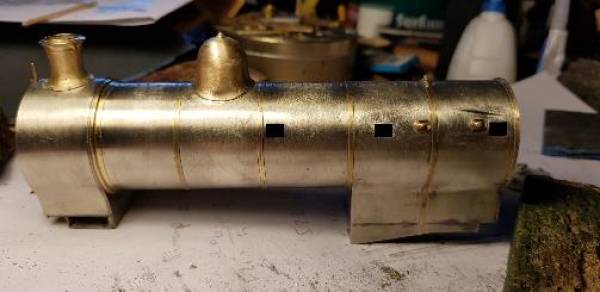
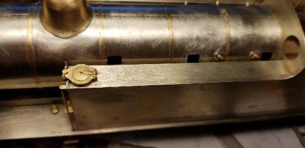
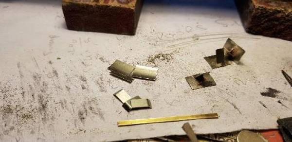
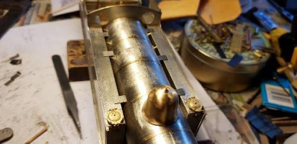
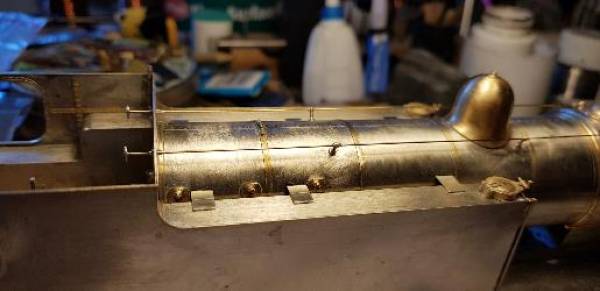


 Now my Scalehardware fake nuts have arrived I can finish the tank brackets…….
——————————————————————————————————–
Nick Dunhill - May 10, 2018 at 8:19 AM
…well my Scalehardware stuff has turned up and I have finished the brackets between boiler and tank tops.
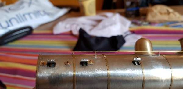
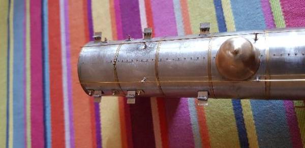
 Also I have made the Westinghouse pump brackets from 0.8 mm sheet brass. They are to be fitted through a hole in the footplate. The dimensions are shown, note the measurements are to suit the Gladiator pump casting which seems to be the best representation.

 More Westinghouse pump fun next…..
———————————————————————————————————-
Buckley10339 - May 10, 2018 at 5:21 PM
The Scalehardware bolts look the dogs dangleys Nick much better than my attempt with the EDM rivets.
Pat.
————————————————————————————————-
Nick Dunhill - May 10, 2018 at 9:36 PM
…..anyway, the brackets are now in place. I think the pics are pretty self explanatory. The footplate was drilled first to allow a piercing saw blade to be inserted, then off you go, carefully! File and check, file and check, carefully! File into corners with a triangular section needle file. Solder solder, done! I've never made one of these before.
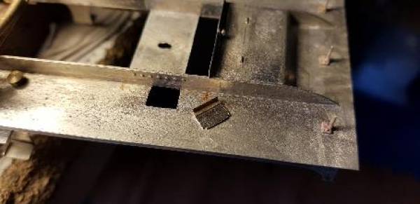

 Next detailing up a Westinghouse pump casting…..
———————————————————————————————————
Buckley10339 - May 11, 2018 at 4:00 PM
Just to highjack Nicks thread for a second and i hope he may have some advice as well about what type of Piercing saw to buy as i am trying to scatch build using some kit parts as patterns two motion brackets for my old Ace V1/3 kit that had been passed on to a friend who has asked me to finish the chassis that i started.I know how they work but have no idea what is the best or most suitable one and of course blades as well.Any hints would be welcome -sorry Nick.
Pat.
———————————————————————————————————
Arun Sharma - May 11, 2018 at 4:31 PM
[B]Saws[/B]
Discussion in Hitns and tips started by David
Saws
This thread should tell you everything you need to know about piercing saws
Arun
——————————————————————————————————
Nick Dunhill - May 11, 2018 at 6:09 PM
Mine came from Manchester Minerals in Stockport. The blades are mainly 6-0 from Eileen's Emporium. I have an old rusty saw with a large loopy frame for large pieces but it's a bit unwealdy and difficult to use.
——————————————————————————————————–
Nick Dunhill - May 11, 2018 at 6:21 PM
….Was going to do the Westinghouse pump but went off on a side quest. I made the control rodding for the blastpipe. It illustrates my descent into madness and proves this is just a vanity project! The rod exits the smokebox on the driver's side and continues to the cab. You can only see most of it if you turn the model over. (WTF Dunhill.)


 Westinghouse pump next. Deffo……
——————————————————————————————————
Nick Dunhill - May 17, 2018 at 12:13 PM
….so I said it was time to sort out the Westinghouse pumps and here we go. Firstly I thought it needed a bit of detailing. There's a fitting atop not on the casting, and it has a flange with a weird Y shaped web and some rivets. The flange was fashioned from some left over etched discs and a fabrication was added from telescoping tube. The assembly was added to the top of the pump with the cast lubricator supplied. The pump also has an upside down T shaped guvnor sticking out of the left side. This was made and attached.
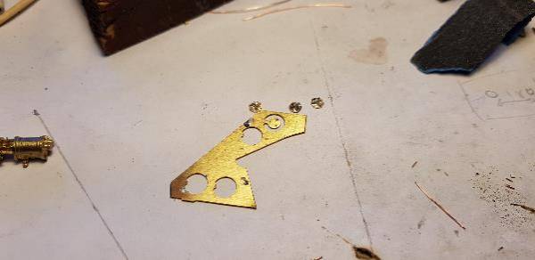
 The modified pump was then offered up to the mounting bracket and soldered in position. All the pipework was then attached.

 The last job on the bodywork is to make the handrail. I'm having a problem finding long enough knobs. I need some that are 4.5 mm from base of flange to centre of hole. Does anyone know who makes such an item? I will also be sending the knobs away to be zinc plated so they look like polished steel on the finished model. If anyone wants to have some knobs zinc plated as well get in touch. This makes the process more cost effective……
———————————————————————————————————
Nick Dunhill - May 18, 2018 at 8:13 PM
….so handrails finished. The upperworks of the build is now complete, just the chassis to go then!

 Should have a little topping off celebration, so I'm off for a beer. More chassis action next……
——————————————————————————————-
Martin Long - May 19, 2018 at 2:55 PM
Nick
Super work as ever. Do myou have any tips as to the best way to get the front handrail which goes over the smokebox? I am wrestling with one at the moment and to get it looking even as to the curvature is nigh impossible but you have done it!
Martin
——————————————————————————————–
Buckley10339 - May 19, 2018 at 3:18 PM
Martin do it in two halves.Slide first one side into the boiler handrails then with the outer hand rail knob pushed into the hole with a dab of superglue put the end into the center handrail knob and file down till its half in then do second side the same and file end to fit in remaining half of the knob with a dab of superglue on it to secure.
its very fiddly but if it goes wrong you have only mucked up one half of it.
Pat.
—————————————————————————————————
Davenport20954 - May 19, 2018 at 11:51 PM
I needed long and short handrail knobs, with a large bore, for the pipes that run down the length of a boiler on a LMS Compound. I think these carried smaller dia copper pipes, looking at my photos of LMS 1000.
I had some brass smoke-box door handles were just right as they had enough material to allow them to be bored out to suit. These came from Markits and they were happy to sell me a selection of just the long handles. Soldered in with a washer behind as reinforcement to the joint.
David
—————————————————————————————-
Nick Dunhill - May 20, 2018 at 10:41 AM
Martin.
All the above are good ideas. Mine was made in one run though, I grabbed a drill with a suitable shank for the curve from side to front of firebox. The rod was curved round the shank to form a 90° curve, then the same drill shank was used to form the second curve that 'joggles' the rod in further to meet the first handrail knob.
I just keep offering up and adjusting and trimming to length to meet the water tank front. Keep everything square. Then I made the big curve round a suitable diameter thing. The nickel silver rod resists this a bit more than brass but persistence will pay off. Then it's back to the drill. The rod has to be 'joggled' back out and curved back round the front of the firebox to meet the next knob, curve first and joggle second.
I had the advantage of being able to remove the boiler but still had to adjust this bit a few times. You can open one end of the curve and close the other to adjust length. Then home to the other tank front. It's a laborious task (sorry I can't offer a secret way!) but the handrail is always a big feature. Different companies had differing curve patterns that are quite distinctive.
My big tip would be not to squeeze the rod too much with your pliers as it will get marked, especially with round ones.
Nick
__END OF WHITBY TANK PART 3_
——————————————————————————————————
_START OF WHITBY TANK PART 4_**
Nick Dunhill - May 23, 2018 at 9:25 PM
….so moving back to the chassis I decided to start with the driving wheel springs and hangers. The hangers were all cast from patterns I made earlier in the build and were designed to be pinned to a set of Laurie Griffin springs that were the right size. The castings were all fettled and holes drilled so they could be pinned together.
 Adjustments were made so they all lined up nicely in the correct positions. They were positioned on the frames and soldered in place. Some cutting was required for the rear sets so they fitted round spacers and laminations, but nothing too drastic.
 Some drop pieces, that connect the spring to the axlebox, and keeper plates were made and soldered to the springs. Adjustments were then made so the springs could be removed to fit the axles, although thinking about it now only the front axle has to be removed downwards if using Slater's wheels. (This will make the second loco a doddle as I haven't started adding the keeper plates it as I write!!) The last 2 jobs had AGH wheels (remember them?) and I'm obviously still in that mind set (it's late, I've been at work all day, etc…).
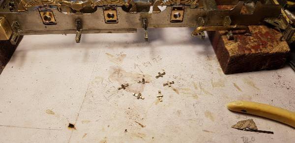

I think I'll have some fun making the various reservoir tanks for the Westinghouse system next…..
Nick Dunhill - May 25, 2018 at 6:12 PM
….I've been having a bit of fun making air reserve tanks for the Westinghouse brake system. They're made from 5/8 and 19/32 telescoping tube. The inner tube was cut 3 mm shorter, and when positioned in the centre of the outer tube supports the end circles and riveted strip.
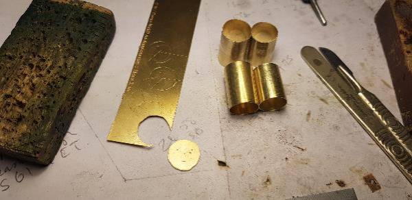


Sorry about the crap pics, they look ok in the 'flesh.' Some pipework next….
Nick Dunhill - May 28, 2018 at 12:11 AM
….so here's one of the tanks attached to one of the models. It was a bit of a faff to fit, held with Blutac whilst the brackets were soldered in place. I am trying to decide whether to make the pipe from it to the Westinghouse pump (routed along the edge of the footplate valence) detachable or whether to install removable sections round the steps to allow chassis/body separation. I'll have the same problem with the heating and brake pipes along the other side of the footplate edge.
 I'll decide in the morning…..
Nick Dunhill - May 28, 2018 at 10:12 AM
I have modelled the drag beam as part of the chassis, actually Mick D put the parts for it on the etchings. When the loco was rebuilt with a bigger bunker the drag beam remained in the original position, so the coupling hook is very long to reach it. I just followed what's on the rebuild GA.


——————————————————————————————–
Nick Dunhill - May 28, 2018 at 7:00 PM
…so I have made the first of the MANY pipes in the Westinghouse system. The long one that connects the pump to the main reservoir is removable so that the steps will clear the pipes when the body and chassis are separated. There's a small pipe that connects the main reservoir with the drivers brake handle at the top too.
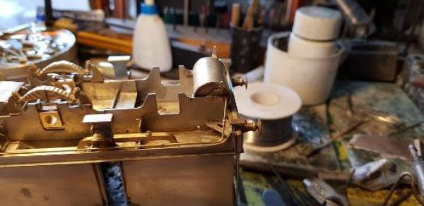


Next I made the auxiliary reservoirs that connect to the brake cylinder. They're mounted under the cab.
 And I've sourced the last of the castings. My triple valve casting and a nice brake cylinder casting from Laurie Griffin.
 The plastic tray has a load of pipe fittings and brackets. More plumbing tomorrow………
Nick Dunhill - May 28, 2018 at 7:00 PM
Tom B sent me this schematic of the Westinghouse system as a guide. Lots of pipes and tanks!

Jim Snowdon - May 28, 2018 at 7:05 PM Those are rather large cylinders for use with air brakes - more like the size of vacuum brake cylinders. Air brake cylinders are normally much smaller, as it is the pounds that do the work, not the square inches. Air brake pressures are around five times those of vacuum brakes, hence the cylinders can be a lot smaller for the same output force. Jim
Nick Dunhill - May 28, 2018 at 7:42 PM
Ah. I think you're right Jim. The ones on the W are 9.8 mm in diameter (scale) so the ones in this pic may be more appropriate. A bit small though.

Nick Dunhill - May 30, 2018 at 5:50 PM
…..well as you can see from my last post I had made the auxiliary air tank and I have since fitted it up to the model and made a connection to the triple valve.
 I have also made an auxiliary-auxiliary air tank and fitted that up, and have also completed the main bits of Westinghouse plumbing.


 ]
Next is the pivot points, shaft and operating arms for the brake cylinder and handbrake……
Nick Dunhill - May 30, 2018 at 5:58 PM I keep looking at the above shot of the loco upside down and wish I'd carried out my idea for cutting away the footplate under the the cab floor. I guess that the footplate does not continue under the cab, and that way the lower pipework could have ended in the vicinity of the upper pipes in the cab. It would have been good to be able to see a representation of the cab floor planking from the bottom of the loco and not a lot of extra effort to achieve it. A veritable nightmare to paint eh WH? Happy Modelling all, see you at Donny…..
Nick Dunhill - Jun 8, 2018 at 6:02 PM
…on with the show! I have made some levers and a brake shaft. everything is made from scrap etch and a bit of rod.

And here they all are fitted up
 I then made some runs of pipe. One goes from the bottom of the Westinghouse valve, across the frame under the large air reservoir, and off to the train brake pipes on each buffer beam. You can also see the train heat pipe that runs from the bottom of the Mason valve to the rubber hoses on the buffer beams. The two runs of pipe are together down one side of the loco and are detachable so the chassis and body can be separated (they interfere with the steps.) The connecting hoses will be added when I get the castings from LGM.
The train heat pipe is the thicker rear pipe. Here's all the pipe fittings pre cut.

More plumbing next, it's nearly all done. just the hoses and feed pipes to/from the injectors……
Nick Dunhill - Jun 11, 2018 at 5:48 PM
…..(nearly) the end of the pipework, just the buffer beam connections to be made for the heat and brake pipes when the castings turn up.) The latest are the feedwater pipes from the rear tank to the injectors (you can see them between the air tanks) and the overflow pipes from the bottom of the injectors to the footsteps.
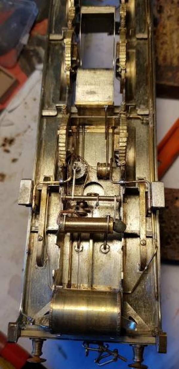

] I wish I could be bothered to polish everything like Richard Lambert and Malcolm Mitchell, but I have since Viakal-ed them to remove all the flux residue and the grott. The tarnish is just heat and abrasion marks……
Davenport20954 - Jun 12, 2018 at 3:22 PM I wonder if a bath of Coca Cola would clean up brass? (other soft drinks are available). I have seen it clean up copper coins in a demonstration of what such drinks can do to your internals. Must try it one day. David
Buckley10339 - Jun 12, 2018 at 3:47 PM A half gallon of malt vinegar from a supermarket in a deep dish works quite well.Left overnight in it a body or chassis is very clean but rather smelly so a wash under the hot tap very quickly is in order.Have used this system for many years with success.One thing to watch is not to spill the vinegar on your workbench it takes a loooong time to get rid of the smell. Pat.
Turnbull21603 - Jun 12, 2018 at 4:02 PM Do you use plain malt vinegar or, white vinegar which works fast but it is a bit aggressive? I assume that copious amounts of water are required to kill any acidic residue. Les
Buckley10339 - Jun 12, 2018 at 7:27 PM Just ordinary Malt vinegar is what i used Les.I read somewhere that vinegar was mildly acidic so a trip to Tesco got me a four pint plastic can. It was very cheap at the time about ten or more years ago but its gone up a fair bit since then so as you can only really do a complete tender loco with it -not all at once - so not as cost effective as it used to be but it does do the job.I never tried the white vinegar, that may last longer and do more models so it may be worth trying.You definitly need to give it a good wash if only to get rid of the smell,i used to soak what had been in it in quite warm water for a while and scrub with a toothbrush - not boiling otherwise you can melt 70° lowmelt solder and unglue superglue on chimneys etc. Pat.
Nick Dunhill - Jun 13, 2018 at 5:11 PM
….right no wheels as yet so on with the motion. Favourites and (slight) fails of Laurie Griffin inside motion parts. The rods are all good castings and tidy up well with an hour or so fettling.


I have bought many sets of these castings in one form or another and these are the first I have had with cast rather than turned eccentric sheaves. I was a bit worried but I needn't have been as they clean up very nicely and are accurately pre-drilled.
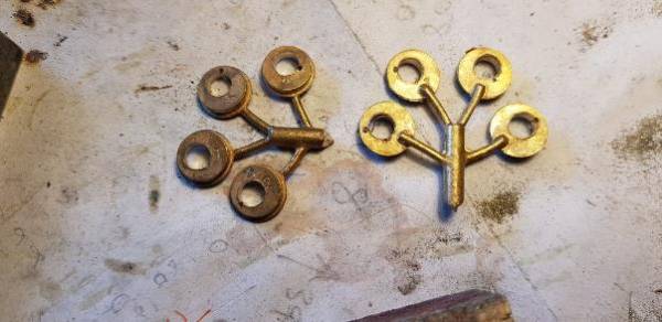

The crankwebb/journal castings are however another matter. Some were distorted and had been drilled when so. Therefore when the castings were realigned the holes for the axles were not concentric. Laurie offered to replace them but I decided to have some made that were thinner to fit in between the horncheeks.
]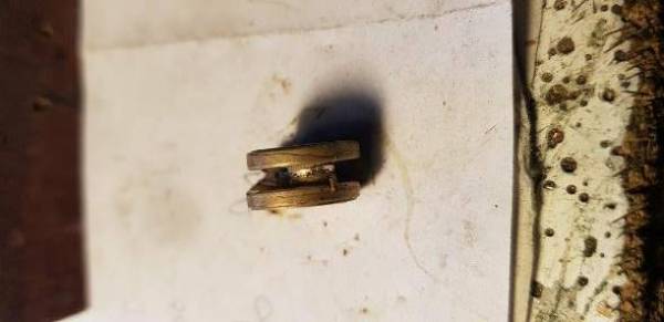

Next more filing……..
Nick Dunhill - Jun 13, 2018 at 10:14 PM
….con rods fitted up…..

Nick Dunhill - Jun 14, 2018 at 8:13 AM . The crossheads and piston glands here are both cast in nickel silver so I think it'll be ok. The main problem I seem to encounter again and again are bent and sometimes inaccurate castings where the piston gland and slide bars aren't central or concentric. Or the crosshead is a bad fit, very rare both come together without a lot of fettling. On the other hand, it's easier to remove metal than put it on.
Nick Dunhill - Jun 15, 2018 at 5:49 PM
…..this is how I made Laurie Griffin eccentric rods. The cleaned up eccentric rod has to be attached to the forked end. The measurements show the centres of the rods have to be 2 mm apart when mounted on the expansion link and eccentric sheaves. The forked ends are offset and the eccentric rod has to go under the shorter side, but only by 0.4 mm, ie not the full thickness of the rod. So;
1 Straighten the cast forked end.
 2 Cut and place in your simple jig. The jig sets the centres at 28.4 mm.
3 Mark out the eccentric rod and cut.
 4 File a step half width.
 5 Replace in jig and solder up.
 6 Use low melt solder as a filler, quickly dabbing on.
 7 File up and polish.
 Done! Repeat 8 times!!…..
DLOS - Jun 15, 2018 at 8:41 PM
Nick, Excellent. Let me whisper in your ear: silver solder ![]() David
David
Nick Dunhill - Jun 15, 2018 at 9:08 PM I know. The problem was that the forked ends needed to be repaired first. They'd been pre-drilled inaccurately, and I had to fill the holes with solder and re drill. If I'd silver soldered I'd have had to revisit the repairs. Laziness I suppose, they're pretty strong though and bear little load.
Nick Dunhill - Jun 19, 2018 at 10:33 PM …..castings for the air brake and heating hoses have arrived and it allowed me to finish the pipework under the loco. Its all a bit painstaking, but worth the effort (bend , check, bend, check etc)
{{:forum:forumlocos:whit4_43_.jpg?600|}}{{:forum:forumlocos:whit4_44_.jpg?600|}}{{:forum:forumlocos:whit4_45_.jpg?600|}}
The pipe to the rear brake hose goes from a T-piece from the air pipe under the main air reservoir, and passes diagonally up to the bufferbeam.


The air brake hoses are detachable for painting, you can see the above one is a bit skewiff. Finishing off Stephenson link motion next……
MartinShaw - Jun 21, 2018 at 11:39 AM Nick Jim Full size Westinghouse pipes are typically 1“ dia and steam heat 2” dia, which equates to more or less 0.6mm and 1.2mm. It was I think fairly rare for steam pipes outwith the cab to be lagged, but undoubtedly different railways had differing approaches. Regards Martin
StephDale - Jun 21, 2018 at 3:05 PM Martin, The sizes you've quoted sound like pipe sizes (i.e. nominal inside diameter) rather than tube (outside diameter) so I imagine something somewhat larger than the sizes you've quoted will be required? Steph
Tom Burnham - Jun 21, 2018 at 5:50 PM If it helps, here is an extract from the NER Class W Pipe and Rod Drawing that Nick used, showing both the steam heat and Westinghouse pipes, together with a nearby dimension of 6“. By printing it at a large scale and using proportional dividers set against the 6” dimension and an actual 6“ rule the steam heat pipe comes out at 1.75” and the Westinghouse 1.25“. Tom.
{{:forum:forumlocos:whit4_2_.png?600|}}
———————————————————————————————————– MartinShaw - Jun 21, 2018 at 8:27 PM Steph is correct, my given dimensions are ID. I suspect steam heat size was selected so that works only needed to stock one pipe size for both vacuum and steam heat, of course you don't really need 2” pipe for steam at 60psi. On that basis Tom's info suggests that 1.25“ for westo pipework is about right giving a pipe wall of 0.125”, but on that I would expect steam heat to be 2.25“. Darlington could well have had a different view, and at the end of the day who am I to gainsay Nick anyway, it is a stunning piece of modelling. Regards Martin
Nick Dunhill - Jun 27, 2018 at 10:20 PM
..I think the real problem is that the hose pipes, and definitely their fixed pipes are over scale. I suspect this may be because they're easier to cast if too big. So 0.1 mm later we're on to the inside motion. The crank castings in the LGM inside motion set have gone to be recycled into steam heat pipes and these fab things appeared. They were kindly machined for me by a sympathiser.

I contacted LG about the cranks and he admitted to a bad set of castings but assured me that the current batch are fine. As previously mentioned the rest of the castings in the set were also fine, so were fettled. The lifting links have to be scratchbuilt, and the balance weights supplied are also the wrong pattern, so replacements have to be made.
The valve rods were made and fitted up. They're made from the usual selection of thin walled tube rods and screws.
 And to bring you all up to date a couple of test fits were performed.


So tomorrow its time to install it all in the chassis…….
Nick Dunhill - Jun 27, 2018 at 10:51 PM I'm going to say something that may be a bit controversial, which I may delete in the morning too! I've had the privilege of having a couple of Beeson models cross my bows and a couple by Tony Reynolds, and have seen a James Harwood production. They are all accomplished modellers but IMHO (me, humble, as if!) Beeson has certainly been usurped by James and Tony. This is probably because, as in most things, the march to 'raise the bar' continues. Beeson was the best of his era but Tony and James share the crown now. Also, as a regular attendee at Guild events, and through my involvement in the Guild's Modelling Competition (get yer entries in folks…) I can appreciate how the march of technology such as CAD driven photoetching and 3D printing has elevated current modellers further still. There are folks around already achieving comparable standards. These days the skill is not so much a case of turning the wheels on a machine tool but driving the software.
Nick Dunhill - Jun 30, 2018 at 9:19 AM
….well here it all is kind of fitted up. I can't get the big end caps on until I've cut the axles, so I've nearly come to an impasse. David White (Slater's) has promised an exciting new range of NER wheels, double sided (i.e. not flat on the back and with full profile spokes) and with all the correct detail. However they're still not available yet and the only bits of this build left are the bogie, radial truck, brakes and sand pipes. All these things require wheels!


——————————————————————————————————-
Nick Dunhill - Jul 2, 2018 at 5:28 PM
…..so, I have made and installed some guides, as per drawing, for the radial truck. My drawing has no detail whatsoever of the make up of the radial truck. Does anyone have a picture or drawing of one that may be similar?


Thanks………….
Tom Burnham - Jul 2, 2018 at 7:25 PM Hi Nick, This is a drawing of the radial axle designed by T. W. Worsdell for the G.E.R. Class G14 and as used on the N.E.R. Class A 2-4-2T,
{{:forum:forumlocos:whit4_3_.png?600|}}
and here is the arrangement of the radial axle for the N.E.R. Class B 0-6-2T reproduced from [I]The Engineer[/I], 23 Nov 1888.
 The Darlington Drawing List at the NRM also has under drawing numbers 741 and 742 a radial axle box, probably for the N.E.R. Class B, and drawing number 7597 for the N.E.R. Class Y, which may be more suitable as it is closer to the date of the Class W.
Cheers, Tom.
Nick Dunhill - Jul 2, 2018 at 9:29 PM Brilliant thanks Tom. Anyone know where I can get some plastic operating (wagon?) springs to make it centering/side control?
Nick Dunhill - Jul 4, 2018 at 5:39 PM
…..so here's the radial truck under construction. No secret just lots of measuring and sanding…
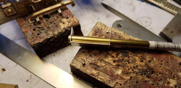

————————————————————————————————————- RobPulham - Jul 4, 2018 at 10:14 PM Which ones did you get in the end from Dart Nick?
Nick Dunhill - Jul 4, 2018 at 10:36 PM They were some MR types with about the right curve on the spring Rob
Nick Dunhill - Jul 5, 2018 at 6:39 PM
…the radial truck for the W class is now complete and installed. It (I hope) captures the appearance of the prototype. Side control is achieved using two tiny coil springs, with a slightly bigger one for downwards force.

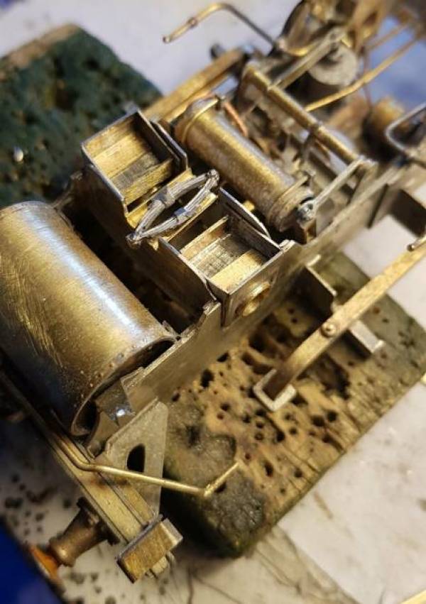

Front bogie next. Hopefully slightly less challenging……
Tom Burnham - Jul 7, 2018 at 12:06 PM Nick, I think you'll find the bogie just as challenging as it also features a curved slide, controlled by two plate springs, as shown in this drawing of the standard N.E.R. bogie.
{{:forum:forumlocos:whit4_67_.jpg?600|}}
Unfortunately the Darlington drawings for the Class W do not appear to have survived but you will be able to refer to your photo's, reproduced here, of the similar Class X and Y bogie drawing for adding detail.

 Tom.
Tom.
————————————————————————————————–
Nick Dunhill - Jul 17, 2018 at 8:43 PM
…before I started with the bogies I prepared all the brake parts. I can't really get much further assembling the brake system until I have some wheels. They're going to be made available by Slater's quite soon I understand, hope so!
 I cut out the name plates too. A sign the end is near when I cut out the plates! (If anyone is doing pre-grouping NER and wants the spare pair of plates get in touch.)
I also prepared all the etchings for the bogie and got some suitable spring castings from LGM (they're GWR ones I believe,) they required the fixings cutting off and straightening slightly. This was achieved easily by carefully gripping them in 2 pairs of pliers and bending to the required deflection.
 The horn guides on the bogie sides were detailed up using NS strip suitably embossed with rivet heads and the triangular gussets added.
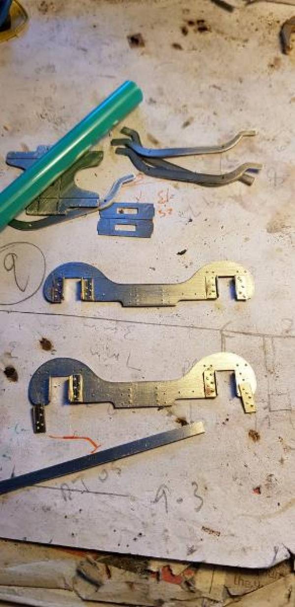

The guides as supplied on the etches can be used straight if you prefer, but as can be seen above in Tom's post they're actually curved. I had to cut a bit off the top of each guide, as it won't now be located in an half-etched slot. The guides were gently curved and the stretcher was folded up with the curved guides held captive.

A simple die block was made as a slider which was held captive with a couple of strips of brass. The side plates were attached using the half etched locating slots.


The equalising beams were made up from the etches and cast springs. A simple jig was made to facilitate this and 8 drop links (per bogie) for the springs were also made.


This is how the beams look when removed from the jig.
 A block and oil box was added to the ends of each beam.

The beams are simply then added to the sides of the bogie frames, this required some cutting away of the inner triangular strengthening gussets on the horn guides. This is the result.
 I need to add some axleboxes and keeper plates, and some plastic (cosmetic) wagon springs for the side control. Plus I need to work out how best to make the side control work (suggestions welcome, but I'm looking for something unobtrusive.)
Of course if you are building one of these yourself and don't mind them not being compensated LGM does some nice cast ones. It will save a couple of days fabricating! http://www.lgminiatures.co.uk/product/1-001-ner-f-m-class-locomotives-etc/ This marks the end of the etches Mick and I produced for this loco. There have been no further mistakes in the sheets other than the ones outlined earlier in this thread. Thanks for your help Mick it was invaluable. Has anyone had any of the S7 Britannia wheels off Slater's? If so what diameter are the bogie and pony axles? Next I finish off the bogies and do some painting and decorating in our house whilst patiently waiting for wheels……
Nick Dunhill - Jul 26, 2018 at 7:36 AM
…..the lovely weather has brought about a reduction in modelling and an increase in motorcycling. This week though I have managed to make some horn blocks for the bogies. If I had a laithe and mill these would have taken an hour or two. I haven't, so they've taken a week. They're made from lengths of tube cut to size in the chuck of my mini drill and plates for the front and back of the bearing. The plates are made by opening up a hole and cutting out a rectangle round them. They sandwich the horn cheeks as they do in the real thing. The axleboxes are prevented from rotating by soldering some appropriately sized channel inside the bottom.


I will make some keeper plates next, then finish the dummy and real side control stuff…..
Nick Dunhill - Jul 28, 2018 at 5:33 PM
…..I have added the plastic wagon springs that Rob Pulham supplied (many thanks buddy) and added a bit more side control detail. I also made the keeper plates for the horn blocks from tube and left over Scale Hardware fake fasteners.
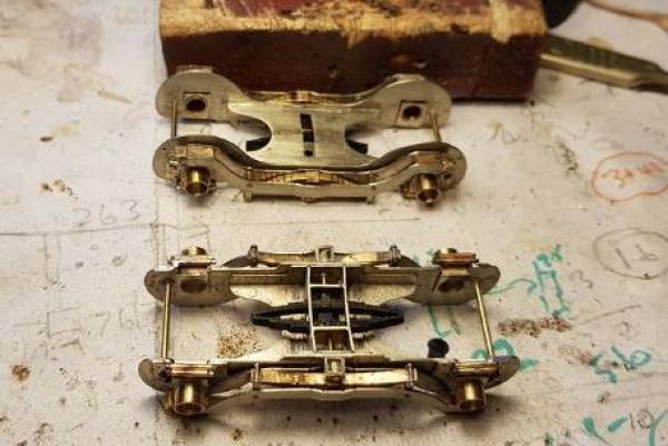

Nothing more I can do now until Slater's have manufactured the correct wheels for the loco. They're imminent I'm told. Here are the two finished locos sitting patiently on our attic bed waiting for the final flurry.
 I have ordered 'kits' for all the people that have asked for one, to be delivered at Telford. Anyone who fancies a set of parts to make one of these mahoosive tanks should get in touch quickly. I have 2 sets of parts left that are for sale for around £200 each (+ P&P, depending on any price increase from the etching company) and once the last two have gone that's it, no more!……..
Nick Dunhill - Jul 31, 2018 at 9:34 PM
…A last peek at the model before I go on holiday. I had to move the injector overflow pipes (the ones behind the cab step bottoms) further to the rear to avoid a conflict with the wheel flanges. This is my favourite part of the model, I obsess about the underside detail. I like making all the tiny fittings and runs of pipes (in the cab too!)
 Finished apart from fitting up the wheels. Just realised no brakes or sand pipes. It's finished apart from the sand pipes, brakes and wheels…….
Davenport20954 - Aug 1, 2018 at 9:58 PM Perhaps you could share your 'clean up' tips. With all that fine detail it must be time consuming unless you built a miniature bead blast machine to do the job. Enjoy the break. David
VigorousKingslynn - Aug 1, 2018 at 10:58 PM I agree about the clean-up tips. You appear to be using a coarser fibre glass brush than I do but still getting into the corners better than I do. There are always corners where only the end of a pin can get to clean - how do you deal with them? John Hobden
Nick Dunhill - Aug 2, 2018 at 5:25 AM Hi John. I wash scrupulously after every session. So I suppose prevention better than cure. I always use a fibreglass brush sparingly as the fibres always marr the finish. I suppose I don't polish like some builder's do. Nick
Nick Dunhill - Aug 19, 2018 at 5:39 PM ….Got some motors and gearboxes and fitted them up. They're ABC Mini-S types with Canon motors. Brian Clapperton's (ABC) website has a printable page of gearbox templates. I printed one and cut out the Mini-S template and built the ashpan round it. Consequently the motor fits right in with no fenagling required. Good planning for a change! I strengthened the ashpan mounts as the pivot/mount for the gearbox (a U shaped bracket that clasps the rear gearbox pillar) is mounted inside the ashpan assembly. The body and boiler fit perfectly with loads of space for DCC wiring and chips and some extra ballast.
{{:forum:forumlocos:whit4_88_.jpg?600|}}{{:forum:forumlocos:whit4_89_.jpg?600|}}
Next TELFORD yay……
PeteHutch18467 - Aug 24, 2018 at 12:06 PM Nick, This thread was recommended to me as an exemplar of brass kit construction having just started my first brass kit ( see Hutch’s Horrors). Your model really is a thing of great beauty and amazing detail. I cannot tell that you ever used any solder at all!
I understand your desire to model that which cannot ordinarily be seen. It is just satisfying in a way I cannot really explain but it certainly marks out what you have created as being a true model of an original. My first Slaters wagon kit got all the underside detailing and although of dodgy build quality gave me more satisfaction than any of the n gauge RTR stock I ever bought. I do like to see my models running but the pleasure is greatly enhanced now that I have started building my own. However, I can see how for some the pleasure and fun of building models is enough. I look forward to seeing this loco when it has been finished. Kind regards, Pete
Nick Dunhill - Aug 24, 2018 at 6:26 PM
….I wasn't going to do anymore modelling until after Telford, but a rainy day in Sheffield has prevented any motorcycling activity and I've come to a temporary break in the punishing schedule of household decorating chores. Someone pointed out to me that I had missed out the fire iron brackets from the tank top and that they are an interesting thing to model. Oddly the real thing looks like they've been cut out of sheet, so I cut mine out of a 6 mm x 6 mm square. I think the photos are pretty self explanatory.

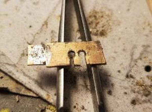

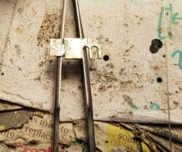


You can see that the NER put a curved bracket at the front too, presumably to stop the irons falling off the tank top. Note to self - buy fire iron set at Telford!…….


