Setting up DJH Jubilee valve gear
Prepared by: Tommy Day
Originator: Sandy Harper
Thread and Forum Title 'A cry for help! (DJH Jubilee valve gear)'.
| Failed to open database: gaugegu1_gog2 | ret is false |
Thread start date Apr 26, 2017
For full Forum thread click here : - Forum article
A dear friend has been building a DJH Jubilee kit but became stuck putting the valve gear together. 'Could I sort it out for him?'
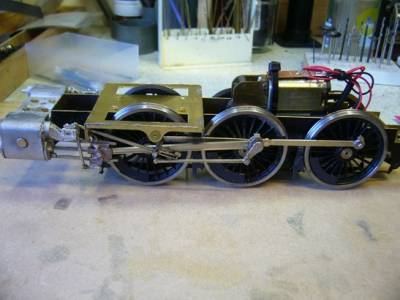
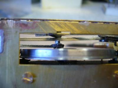
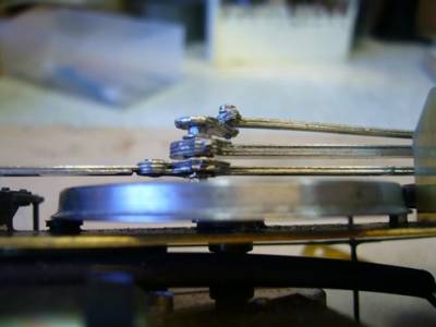
The first photo shows how far he had got with one side. The chassis was well put together but the wheels and motion needed sorting!
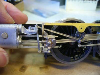
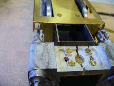
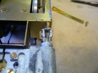
The first thing I noted was that the valve guides did not line up with the holes in the motion bracket and this was causing problems by forcing the white metal guides to distort. Also the motion itself had been soldered together from laminated N/S but the cusp had not been filed off and it looked bad.
Careful study of the chassis photographs will show a number of other issues that I felt also needed addressing.
Badly fitting joints, loose crank pins, clearance issues etc. My first job was to dismantle all the valve gear and remove the wheels. Some of the soldered nuts had to be ground off but I had plenty of replacements and anyway, after inspecting the wheels and crank pins, I was going to replace them with 10BA bolts so that I could use tapped crank pins.
Sandy Harper - Apr 26, 2017 at 6:37 PM
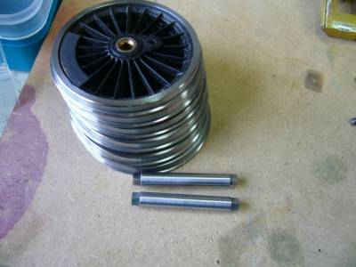
The Slaters 12BA crank pins were loose in the wheels and an attempt had been made to glue them to the wheel also, no countersink had been made in the back of the wheel to accommodate the heads of the crank pin screw.
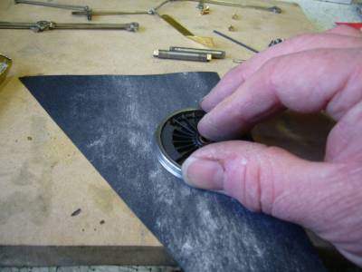
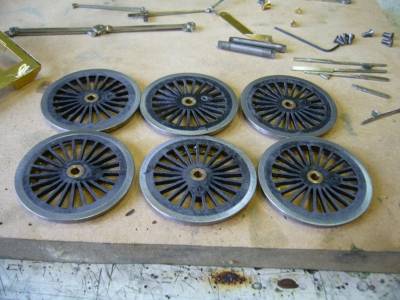
I started on the wheels, rubbing the backs on a piece of wet and dry to ensure they were flat with no extraneous pips or stray bits of the center molding to get in the way of the plunger pickups. I then spun them up in the lathe, along with the axles to get them clean, using a Variflex block. The square ends of the axles were also given a couple of wipes with the file on the faces to make sure there was no burrs and that they fitted the wheel centre boss without forcing them on.
——————————————————————————————————–
Sandy Harper - Apr 26, 2017 at 9:31 PM
To finish of the wheels I fitted 10BA countersunk bolts after tapping the old original holes 10BA and countersinking the rear of the wheel. The next stage was to tap the Slaters crank pin bearings. I need 8 bearings in total as the centre axles needs two bearings each.
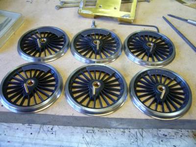
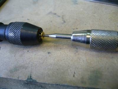
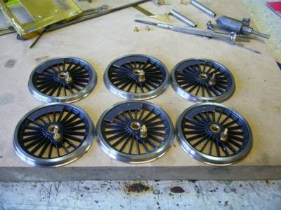
The front crank pin(on the left) is fitted in reverse to obtain as much clearance as possible between the crank pin and the rear of the cross head. Two 10BA washers need to be fitted up against the wheel to allow the rod to clear the axle nut. The centre wheel has one bearing fitted normally, then a washer followed by a bearing reversed as per the front wheel. The rear wheel crank bearing is fitted as per Slaters instructions with a washer and nut (10BA) apart from the fact it is screwed on to the pin. I have now worked on the rods and slide bars and will photograph them tomorrow. Sandy
Bob Alderman - Apr 26, 2017 at 9:50 PM
Sandy I have built one of these kits and I used the etched valve gear. For whatever reason it is the free-est running loco I have ever made. For that little problem inside the valve spindle cross head I soldered a rod into one half of the fork and simply filed both sides flush so the joint fitted in the gap. The fork with the valve rod below was similarly treated. Regret loco not available to photograph. Bob
Sandy Harper - Apr 27, 2017 at 8:23 AM
Whilst fiddling about with the cross head, to ascertain clearance for the front crank pin, I noticed that the cast cross head was 'crabbing' along the slide bars as if the bearing slots were too wide! Closer investigation identified that it was the slide bars that were too narrow. On checking the 'box of bits' that came with the chassis I found the third lamination that makes up the slide bar still attached to the fret! The slide bars had therefore to be removed from the cylinders and the missing lamination added. Fortunately, with the application of a little heat, they slid out and I was able to sweat on the missing part and clean up before sliding them back in.
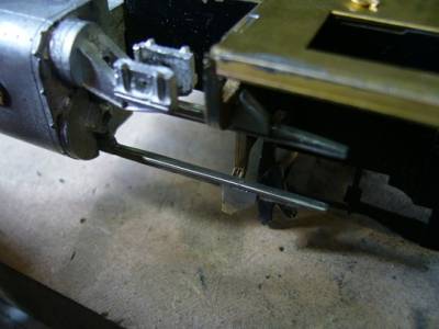
Next I tackled the rods. As already mentioned above, the correct construction of etched rods can give a more realistic profile than '2D' milled rods so I set about them with copious amount of solder and files and the result was very pleasing and certainly better that before!

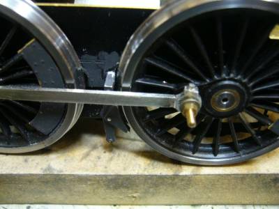
Regards Sandy
Sandy Harper - May 3, 2017 at 7:43 AM
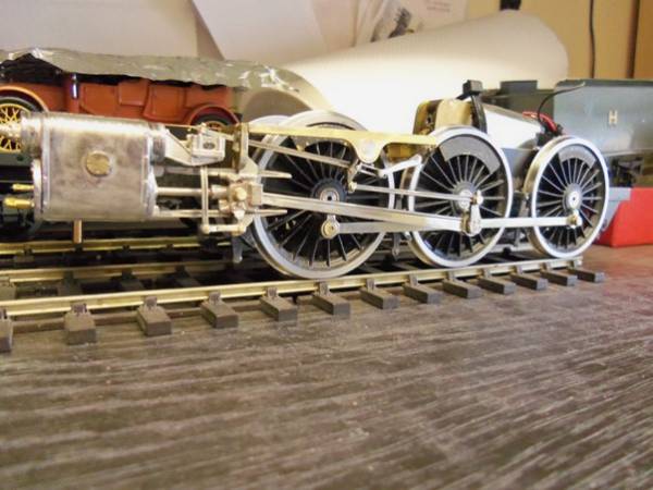
There we go! One side complete. Note, gear is in forward gear. Makes the valve rod move which I think looks better than the usual mid-gear position. Yes I know it looks wrong in reverse but it is only wrong for about 10% of the time when running where as neutral is wrong most of the time!!
Regards
Sandy
——————————————————————————————————–
Bob Alderman - May 3, 2017 at 12:58 PM
Sandy That's full forward gear. Mostly used for starting. Any chance of increasing the cut-off and moving it nearer the combination link pivot? A position where spends even more time. Nevertheless it looks to be a very tidy assembly. Bob
Sandy Harper - May 3, 2017 at 5:02 PM
Very true Bob but, there is not a lot of choice in the link pivot by the time you have drilled a hole above or below the central point. Anyway, it doesn't half make the valves work!! I tried to post a short vid of it on the rolling road but the Forum didn't like it. Sandy
End of thread