Weathered Industrial Storage Tank Card Kit
- Purple Bob’s Hobbies,
- Price £11.95 each, post free
Kits purchased and reviewed by Keith Martin
This was not the first Purple Bob kit that I have put together which should tell you immediately something of how I rate these card models. Kits arrive in a stiffened A4 envelope which contains the printed parts on five sheets of card and five pages of instructions. Most Purple Bob kits are for low relief buildings but for this one there is the ability to join two back to back to make a complete tank which is what I have done.
Before taking the modeller through the construction sequence the instructions contain advice on the tools needed to achieve best results and emphasise that completion will take time; glued parts need to dry thoroughly. Apart from the obvious sharp blades and glue another essential requirement is a selection of felt-tipped pens or paints to colour the exposed edges of cut card.
My initial appraisal was that the quality of printing is high and various parts – the steel plating of the tank side, straps, roof structure – use non-repeating patterns of rust and streaking. The card is 0.28mm thick which equates to
12mm at full size. When doubled, as it is for the I beams supporting the outside of the tank, it gives a fair representation of a girder. The design is based on an actual tank that was in use from the 1890s until the 1990s.
 Photo 1
 Photo 2
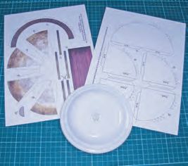
Construction started with the framework (photo 1). In cutting the circular sections I used a plate of roughly the right diameter as a guide. This provided a skeleton on which to attach the tank side (photo 2). Accuracy in scoring and cutting at this stage determines the symmetry of the final structure. The tank side comes as a single piece and it is essential that it sits square on the base; if there are any inaccuracies in the frame, gaps at the vertical edges can be masked by the girders. The pendant triangles seen in photo 2 ensure there is a strong attachment to the frame.
 Photo 3
 Photo 4
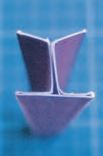
Photo 3 shows the tank side in place and the supporting girders in various stages of assembly and fitting. Photo 4 shows the result of a less-than-totallyaccurate score and fold of an I beam. The other end of the girder is atisfactory but here my scoring and folding is adrift to the order of only 0.5mm. Fortunately when two kits are joined there are two spare I beams. Once the beams are in place straps can be glued horizontally along
the plate joins and along the base and top edge.
 Photo 5
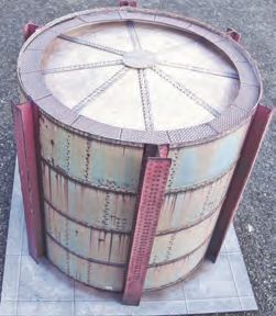
The dome comprises sector plates the joins between which are covered by straps. There is a boss plate to fit over the central join. Finally a chequer plate walkway is glued round the inner edge just below the top. Photo 5 shows the roof construction under way and Photo 6 shows the completed structure. The framework within gives a solid feel to the finished model.
 Photo 6
The kit builds into a good representation of an anonymous industrial tank. The half tank is 165mm high standing on a base 192mm wide by 96mm. The diameter of the tank is 174mm including girders. Modellers can add pipes, valves
or graffiti. If there is a shortcoming with my finished model it is one that arises only when building a 360 degree tank. Before fixing the roof I should have coloured the inside of the outer shell below the top strap and the back of the triangles that secure the walkway. From some viewpoints it is still possible to see white card below the finished walkway, just visible in photo 6, and it is more awkward to remedy after completion. The problem would not arise with the low relief version sat on a layout facing forwards.
I am pleased with the finished product. It differs from the usual shape and range of kits offered on the O gauge market. It was fun to make and I can rerecommend it to anyone looking to add an unusual feature to their layout.